Published:2026-10-29 00:00:00
Updated:
Support units · Shaft-end interfaces
Separate the working screw from its bearing and drive interfaces
The threaded section, bearing journal and coupling extension of one ball screw can have different diameters. Verified catalog examples show how to connect model selection, end drawings and assembly checks.
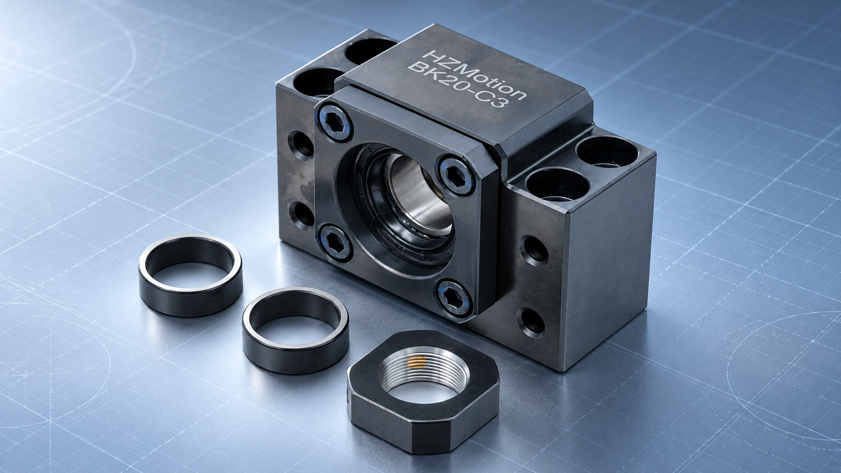
01 / Identify the dimensions
Different shaft diameters serve different interfaces
A ball screw specified with a 16 mm nominal diameter may appear beside a BK12 support unit on the same purchase order. That is not necessarily a mismatch. The nominal diameter describes the threaded working section; the support unit fits a machined bearing journal. Once those locations are separated, the numbers become useful rather than confusing. The question is whether every end feature can locate, clamp, seal and transmit motion as the drawing requires.
| Dimension or designation | Physical function | Check against |
|---|---|---|
| Nominal screw diameter | Describes the threaded working section; relevant to load, stiffness and speed checks | Ball screw selection and nut specification |
| Bearing journal d₁ | Fits the bearing inner ring in the support unit | The shaft-end drawing for the exact support model |
| Shoulder and abutment face | Locate the inner ring, sleeve and other stack components axially | Shoulder height, usable contact face, fillet and axial stack |
| Locknut thread M | Receives the locknut used in the specified clamping arrangement | Diameter, pitch, usable thread length and thread relief |
| Drive extension | Connects the screw to the coupling hub | Hub bore, engagement length and connection method |
| Supported-end features | Fit the opposite bearing and its axial locating arrangement | The supported-end drawing, not a copy of the fixed end |
These dimensions are related, but none can replace the others. A coupling with the correct bore proves only one interface. A journal that enters the bearing does not prove that the shoulder, locknut thread and sleeves form the required assembly. Manufacturing, purchasing and inspection should all refer to the same complete shaft-end drawing and revision.
This article addresses model and geometric compatibility. Load capacity, life, critical speed, buckling and stiffness still require separate checks for the application. A geometric fit is not a performance approval.
02 / Verified catalog example
How to read the HZMotion BK table
Section 7.1 of the HZMotion support-unit manual gives BK fixed-end units and their associated screw-end designs. The following four rows illustrate how to read that relationship. The listed screw diameters are the manual’s stated application range; they do not replace the application load, travel, mounting arrangement or complete end drawing.
| Fixed-end model | Listed nominal screw diameters / mm | Bearing journal d₁ / mm | Locknut thread M in this drawing |
|---|---|---|---|
| BK10 | 12 / 14 / 15 | 10, tolerance zone g6 | M10×1 |
| BK12 | 14 / 15 / 16 | 12, tolerance zone g6 | M12×1 |
| BK15 | 18 / 20 | 15, tolerance zone g6 | M15×1 |
| BK17 | 20 / 25 | 17, tolerance zone g6 | M17×1 |
For BK12, the number 12 corresponds to the bearing journal in this table. It does not require a 12 mm threaded working section. The manual lists 14, 15 and 16 mm screw diameters for this unit. Conversely, a 20 mm nominal screw appears in both the BK15 and BK17 rows. Nominal screw diameter therefore cannot uniquely select a support unit.
The g6 designation is also specific to the referenced end design. It is not a universal tolerance rule for every ball screw journal. Different support families, bearing arrangements or special accuracy requirements require their own drawings. Determine the actual size limits from the applicable drawing and standard; do not interpret “12 g6” as an instruction to manufacture every part at exactly 12.000 mm.
Source: HZMotion Chinese support-unit manual, section 7.1, PDF page 13. The complete drawing also defines axial lengths, sleeves and mounting geometry. This shortened table is not a manufacturing drawing. Open the source manual.
03 / Matching sequence
Choose the load path before freezing the shaft end
A practical way to reduce rework is to separate performance selection from geometric matching, then join them through one interface record. First choose a support arrangement that meets the application. Next match both shaft ends to that arrangement. Starting with an already machined end and accepting whichever support slides onto it can overlook stiffness, axial restraint or mounting space.
- Define the axis dutyRecord axial loads, moving mass, acceleration, speed, travel, orientation and accuracy target. Identify the drive and supported ends.
- Select the arrangement and complete modelCheck the axial load path, available space and machine interface. Record suffixes and any agreed accuracy or configuration options.
- Obtain the two end drawingsCheck fixed and supported ends separately: journals, shoulders, threads, reliefs, extensions and axial locating features.
- Include the coupling and bracketCheck usable hub engagement, shaft-end spacing, access for tools and the support mounting datums.
- Freeze one drawing revisionThe screw supplier machines to the approved end drawing; the support supplier delivers the complete specified model. Assembly and inspection use that same revision.
During a repair, the removed part is useful evidence but is not a substitute for the original drawing. Journal wear, nonstandard sleeves, previous modifications and superseded components can make a simple dimensional copy misleading. Retrieve the original drawing number, complete part code and assembly record first; use measurements to verify them and fill genuine gaps.
Application → support arrangement and model → both shaft-end drawings → coupling and mounting stack
A review sequence, not a calculation. Keep the drawing number, revision and measurement evidence associated with each step.04 / Close the interface loop
From sliding on to assembling correctly
Axial clamping can involve a shoulder, bearing inner rings, sleeves and a locknut. If any feature contacts too early, the nut can feel tight while the intended abutment remains open. Check radial fits and axial contacts together; a single diameter measured with a caliper cannot establish the entire match.
| Interface | Review together | Possible consequence of a missed detail |
|---|---|---|
| Journal and entry | Diameter limits, usable length, chamfer and surface condition | A burr or size error causes abnormal assembly force and can damage the mating surface |
| Shoulder and inner ring | Height, datum face and clearance between fillet and bearing chamfer | The fillet contacts before the intended flat faces meet |
| Sleeves and seals | Correct part, orientation, contact path and sealing surface | An incorrect sleeve changes the axial stack; a seal may run on an unsuitable surface |
| Locknut and thread | Pitch, full usable thread, relief and tool access | The nut reaches a thread limit before the specified stack is seated |
| Drive extension and coupling | Bores, engagement, shaft-end spacing and removal access | Shaft ends touch or a hub clamps over a chamfer or relief |
| Supported end and machine | Specific end design, axial restraint, center height and mounting holes | Only the fixed end has been matched; the other bearing or machine interface is incompatible |
Distinguish the preload established by the matched bearing arrangement from the clamping of that arrangement onto the screw. Arbitrarily increasing locknut torque is not a way to correct an incompatible shaft end. If starting torque or rotational resistance rises substantially during the prescribed assembly sequence, investigate contact, alignment and stack dimensions before applying more force.
For a fixed–supported arrangement, confirm where and how the design provides axial restraint and any intended accommodation of thermal movement. The word “supported” alone is not authorization to remove a retaining ring, change a fit or alter clamping. Those details belong to the model drawing and complete axis assembly.
05 / Purchasing and handover
One record for supply, machining and inspection
A useful matching record answers three questions: what to purchase, what to machine and what to verify after assembly. The following fields can be added to an inquiry or drawing approval sheet. Mark an unknown item as awaiting confirmation instead of silently assuming it matches the old component.
| Record | Information required | Confirmation evidence |
|---|---|---|
| Screw working section | Nominal diameter, lead, accuracy, travel and operating load | Application and sizing record |
| Both support units | Complete fixed-end and supported-end codes, including options | Supply list and applicable manual or approved drawing |
| Shaft-end drawings | Left/right drawing numbers, revisions, datums, tolerances, surface and heat-treatment requirements | Manufacturing confirmation of the drawing |
| Associated parts | Sleeves, locknut, retaining parts and orientation | Bill of materials and assembly section |
| Drive interface | Coupling model, both bores, engagement and spacing requirements | Coupling drawing and installation instructions |
| Acceptance evidence | Critical dimensions, face/runout checks and assembled rotation checks | Inspection record and axis acceptance criteria |
For example, an engineer first confirms BK12 for an axis and obtains the applicable end design. The manufacturing drawing retains a 16 mm working-section specification and the specified 12 g6 bearing journal, then defines the drive extension required by the actual coupling. Purchasing confirms the full BK12 configuration, while inspection measures against the released shaft drawing. The numbers 16 and 12 now have distinct, traceable meanings.
This is an information-control example, not a universal configuration for every 16 mm screw. Changes in load, speed, stiffness or installation space require a return to the selection conditions. Once the interfaces are established, continue with ball screw end machining and assembly fit inspection for checks on the finished component.
06 / Frequently asked questions
Decisions that deserve a drawing check
Does BK12 mean a support for a 12 mm nominal screw?
Not in that reading of the referenced HZMotion table. BK12 has a 12 mm bearing journal and lists nominal screw diameters of 14, 15 and 16 mm. Final selection still requires the duty and complete end drawing.
Can different support families with the same number be exchanged?
The number alone does not establish interchangeability. Bearings, center height, mounting holes, axial lengths, sleeves and locking arrangements may differ. Compare both drawings and the application requirements.
Why can a shaft end fail to seat when its diameter appears correct?
Possible causes include fillet interference, burrs, journal length, sleeve orientation, insufficient usable thread or shaft-end contact. Identify the actual contact rather than pulling the assembly together with extra force.
Is g6 the correct journal tolerance for every support unit?
No. Here it belongs to the listed BK shaft-end design. Other families and special configurations require their own approved drawings.
Are a screw diameter and photograph enough for an inquiry?
They can support initial identification, but final confirmation needs complete part codes, both end drawings, coupling and mounting interfaces, and key operating conditions. State whether a used part has been modified or worn.