Published:2026-10-29 00:00:00
Updated:
Shaft-end machining · Fit inspection
Connect dimensional conformity to correct, repeatable assembly
Inspection is about more than journal diameter. Shoulder seating, fillet clearance and a reachable clamping position also determine whether the finished end can assemble as intended. Record those relationships so the result can be checked again.
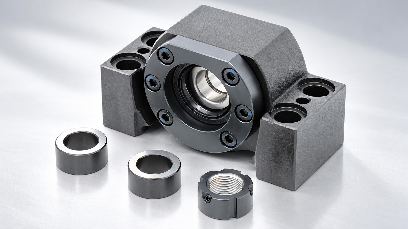
01 / Functional zones
Check each locating and clamping surface
The support model has been selected and the journal diameter has been measured, yet assembly can still reveal an unseated face, a locknut that stops too early or increased rotational resistance. The investigation needs to move from one dimension to a chain of contacts: which face locates, which face clamps, which feature needs clearance, and which surface must also serve a seal or coupling.
This article follows model matching and addresses the inspection of a finished shaft end. Use the approved machining, support-unit and assembly drawings as the basis. Do not infer tolerances from a product photograph. Before measuring, confirm drawing number, revision, left/right end and complete model so that the correct table is not applied to the wrong component version.
| Functional zone | Main role | Inspection focus |
|---|---|---|
| Bearing journal | Provides the radial fit to the inner ring | Size limits, usable length, surface condition and specified geometry |
| Locating shoulder | Provides an axial abutment for the inner ring or specified sleeve | Face location, support area, fillet clearance and datum relationship |
| Sleeve/seal section | Transfers axial clamping or provides a sealing surface | Sleeve direction and length, sealing surface and transitions |
| Locknut thread | Allows the nut to reach the intended clamping face | Pitch, usable thread, relief, face condition and tool access |
| Coupling extension | Transfers drive torque into the screw | Bore/shaft compatibility, engagement, keyway and end spacing |
| Supported-end location | Fits the opposite support arrangement | Specified shaft sections, grooves, retaining parts and contacts |
A single step can affect several functions. A shoulder fillet influences bearing face seating, while an adjacent relief changes the usable fit length. Dividing the end into zones makes inspection clearer, but the final review must return to the complete assembly section and confirm that all intended contacts can coexist.
02 / Shoulders and fillets
Eliminate transition interference before judging face seating
A shoulder is an active axial locating surface, not merely the result of a diameter change. The bearing inner-ring face must meet the specified abutment. If the shoulder fillet contacts the bearing chamfer first, the bearing can appear installed while the intended flat faces remain apart. Further locknut tightening creates abnormal assembly force; it does not prove the geometry is correct.
| Feature | Relationship to confirm | Method and limit |
|---|---|---|
| Fillet and bearing chamfer | The transition has the clearance required by the design | Compare the shaft and bearing drawings; use suitable profile measurement where required |
| Shoulder face | Specified geometry relative to the required datum | Establish the drawing datum; apparent visual flatness is not a face inspection |
| Usable abutment area | The contact area meets the design without interfering with other features | Review the section and actual contact region; do not enlarge the shoulder arbitrarily |
| Relief and transition | They do not occupy the required bearing, sleeve or hub fit length | Check axial position and diameter, not groove width alone |
| Entry and surface condition | No burr, damage, debris or machining condition that prevents proper assembly | Clean, inspect and measure; uncontrolled polishing must not alter a functional fit |
There is no universal fillet radius or face-runout value in this guide. Bearing chamfers, shoulder heights and arrangements differ; an accepted value for one model cannot simply be transferred to another. If the drawing does not provide enough information to judge the interface, complete the design requirements before deciding how much material to remove at the assembly bench.
The catalog end design must also correspond to the actual configuration. Section 7.1 of the HZMotion BK manual shows bearings, sleeves, seals and locknut in one section alongside the end dimensions. That view helps establish contact order, but it does not replace the machining tolerances, datums and acceptance requirements for a special part.
03 / Axial dimension stack
Check the clamping position and usable thread separately
After radial dimensions have passed, verify that the assembly can clamp the intended components at the intended location. The nut must reach the required clamping face while remaining within the permitted usable thread region. A bearing, sleeve or other contact part must not be stopped by an unintended step. List only the actual contacting lengths in the stack rather than adding unrelated outline dimensions.
L = l₁ + l₂ + l₃
Lmin = Σli,min; Lmax = Σli,max
| Three illustrative contact lengths | Nominal size / mm | Extreme range / mm |
|---|---|---|
| l₁ | 20.00 ± 0.02 | 19.98–20.02 |
| l₂ | 5.00 ± 0.01 | 4.99–5.01 |
| l₃ | 5.00 ± 0.01 | 4.99–5.01 |
| Total L | 30.00 ± 0.04 | 29.96–30.04 |
These assumed values illustrate the method: nominal lengths total 30.00 mm, while extreme combinations place the contact at 29.96–30.04 mm. Compare that entire interval with the real drawing’s achievable clamping position, usable thread and adjacent steps. Checking the nominal value alone can overlook early contact at a tolerance boundary.
This is a teaching example, not a bearing width, sleeve specification or product stack. It cannot determine bearing preload or tightening torque. Those also depend on the actual structure, materials, contact behavior and installation instructions.
Resistance while turning a nut does not establish that the correct stack is clamped. The resistance can originate from a damaged thread, thread runout or misalignment. If the contact position differs from the drawing, identify the cause. Do not alter a matched bearing arrangement with unapproved sleeve thicknesses, added shims or mixed inner/outer spacers to make a dimensional problem disappear.
04 / Measurement and records
Diameter, roundness and runout are different inspection items
Select a measurement method that can establish the characteristic being reported. Micrometer readings at several axial and circumferential positions can reveal size variation, but they do not automatically establish roundness or cylindricity. Runout includes the variation observed as the part rotates about the established datum; the result depends on how that datum is realized and is not simply “the straightness of the screw.”
| Inspection item | Useful record | Conclusion to avoid |
|---|---|---|
| Journal size | Drawing limits, instrument, temperature conditions and readings at defined locations | One acceptable reading proves the entire journal |
| Roundness/cylindricity | Drawing requirement, suitable method and measured sections or extent | A few diameter readings prove the form tolerance |
| Radial or face runout | Datum, support arrangement, probe location, measured extent and result | All indicator movement comes from the part regardless of fixture error |
| Shoulder and axial lengths | Reference face, contact location, usable length and limits | A critical dimension can start from an undefined chamfer edge |
| Thread and relief | Specification, appropriate checking method, usable thread and reachable position | A nut turns a few revolutions, so the complete thread and clamp position are acceptable |
| Surface and cleanliness | Fit surfaces, transitions, residue and damage locations | Removing visible marks by grinding is an acceptable cure for any defect |
The record should be reproducible: another inspector using the same drawing revision, datum and measurement locations should understand what was checked. Near a limit, consider measurement capability and uncertainty rather than treating the last displayed digit as infinitely exact. Follow the inspection procedure when the environment is not stable, the part is freshly machined or handling has materially warmed it.
For batches, consistent point numbering and inspection order improve efficiency. When a result is abnormal, retain its location and pattern instead of writing only “oversize.” Differences near the shoulder, at mid-length or at the entry can help manufacturing investigate tooling, grinding and workholding.
05 / Trial assembly and handover
Identify which assembly step introduces resistance
Trial assembly checks manufacturing, component configuration and assembly sequence together. It does not replace dimensional inspection. Verify part condition first, then establish the specified contacts step by step. At the defined stages, check location and rotation under the prescribed conditions so that any increase in starting torque or rotational resistance can be traced to a specific change.
- Confirm the partsVerify complete screw, support, sleeve and locknut specifications and condition. Clean and orient them according to the drawing.
- Establish the fit correctlyUse the method and tools appropriate to the actual structure. Apply assembly force to the component being fitted; avoid transmitting inappropriate mounting force through rolling elements.
- Verify the intended seatingConfirm the specified shoulder, inner-ring or sleeve contacts. If unexpected resistance appears, stop and inspect interference and dimensions.
- Tighten to the actual instructionsUse the confirmed locking method, sequence and parameters. Arbitrarily increasing torque is not an alternative to dimensional inspection.
- Recheck at defined stagesCompare the states after insertion, clamping, machine mounting and drive connection. Record the stage where a change appears, then complete axis acceptance.
| Observed issue | Evidence to revisit first | Information for manufacturing/assembly |
|---|---|---|
| Bearing or sleeve does not reach the specified face | Fillet, chamfer, shaft-section length and actual contact | Unseated location, related measurements and photographs |
| Nut stops moving early | Thread, usable length, relief and contact chain | Stop position and the component still not clamped |
| Resistance increases after clamping | Sequence, face seating, axis relationship and sleeve configuration | The triggering step and reproducible measurement conditions |
| Issue appears only after coupling installation | End gap, both engagement lengths and axial installation condition | Positions, spacing and exact coupling model |
If machining is nonconforming, return the repair proposal to design and process review. Record whether rework is permitted and which dimensions or performance characteristics require reinspection afterward. Hammering, uncontrolled journal polishing or pulling the part into place with the nut can conceal the original issue and make future disassembly or accuracy diagnosis more difficult.
06 / Frequently asked questions
Keep the conclusion proportional to the evidence
Does a conforming journal diameter mean the complete shaft end passes?
No. Check axial lengths, shoulder, fillets, threads, usable coupling engagement, and the geometry and surface requirements on the drawing. Confirm the complete contact relationship as well.
How should the shoulder-fillet radius be specified?
There is no such universal value. The bearing chamfer, shoulder geometry, stress and manufacturing conditions must be considered in the approved drawing. A value for one model is not a general rule.
Does resistance at the locknut indicate sufficient preload?
Not by itself. The resistance can come from unintended contact, thread problems or unseated components. First verify the intended clamping faces, then follow the actual arrangement’s tightening and acceptance requirements.
Can several diameter readings replace roundness or cylindricity measurement?
Generally no. They can expose size variation, but roundness and cylindricity have distinct definitions and measurement requirements. Select the method for the characteristic on the drawing.
Can a tightening torque from another support unit be reused?
Do not assume so. Threads, locknut structures, bearings and installation conditions can differ. Use the requirements for the actual model and resolve missing information before tightening.