Published:2026-09-02 09:30:00
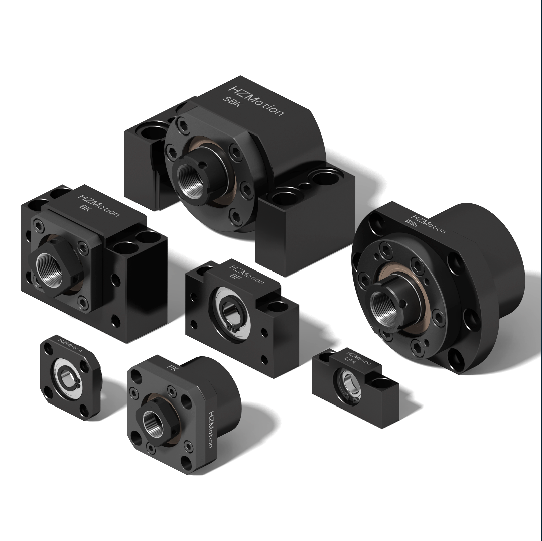
Ball Screw Support Unit FAT / SAT
Free rotation is only the starting point. Acceptance requires repeatable data.
After installation, verify shaft-end radial runout, axial clearance, screw-to-guide alignment, and temperature, current and vibration trends during staged operation. Every result needs an instrument, point, assembly state and governing requirement.
01 / Acceptance basis
Define the governing requirement before placing an indicator
Runout, clearance and alignment limits vary with screw grade, shaft-end geometry, support arrangement, measurement position and machine accuracy target. Cite a controlled document and revision instead of an unverified “universal tolerance.”
| Requirement level | What it controls | How to use it |
|---|---|---|
| Approved machine or axis drawing | Parallelism, coaxiality, runout, axial clearance and error budget | Final numerical criterion; record drawing and revision |
| Screw and support-unit documentation | Shaft tolerances, housing datums, locking, load boundary and mounting | Define the object, method and product boundary |
| Project FAT / SAT specification | Instrument, point, speed stage, dwell and stop condition | Put supplier and customer in the same test state |
| Qualified baseline | Temperature, current, vibration, noise and repeat trends | Trend comparison, not a replacement for mandatory limits |
If no number is specified: record the measurement and submit it for engineering/customer approval. Do not invent a generic acceptance limit.
02 / Preparation
A reading cannot be compared unless the assembly state is frozen
Verify complete screw, fixed-side, supported-side, locknut, coupling and motor model numbers, drawing revisions and arrangement.
Record indicator ID, resolution and calibration. Clean all machine, guide, housing and probe contact surfaces.
State coupling connected/disconnected, bolts temporary/final, table position, ambient and initial axis temperature.
03 / Alignment and tightening
Temporarily fasten, align by reciprocating, then tighten and remeasure
- Inspect mounting datumsConfirm support heights, holes and guide references. Do not force a bad base into position with bolt load.
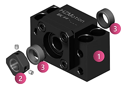
- Install both endsProtect seal lips and do not disassemble a factory-preloaded, grease-filled fixed-side unit. Follow the model instruction for shaft locking.
- Temporarily fasten all jointsConnect the ball nut, nut bracket and both support units while retaining alignment freedom.
- Reciprocate through full travelMove toward both ends and watch for local binding, current change and center shift. Use controlled shimming or locating fits as specified.
- Apply the controlled sequenceFollowing the manufacturer procedure, tighten the ball nut, nut bracket, fixed-side housing and supported-side housing, checking motion after each stage.
- Remeasure and secureAfter runout, clearance and motion pass, secure setscrews, thread locking and witness marks as required.
Keep fasteners separate: the shaft locknut locates the bearing stack on the screw; housing bolts locate the support unit on the base. Their purposes, torque references and checks differ.
04 / Points and methods
Use the same support, point and assembly state for repeatable data
| Check | Instrument and point | Method | Record | Criterion |
|---|---|---|---|---|
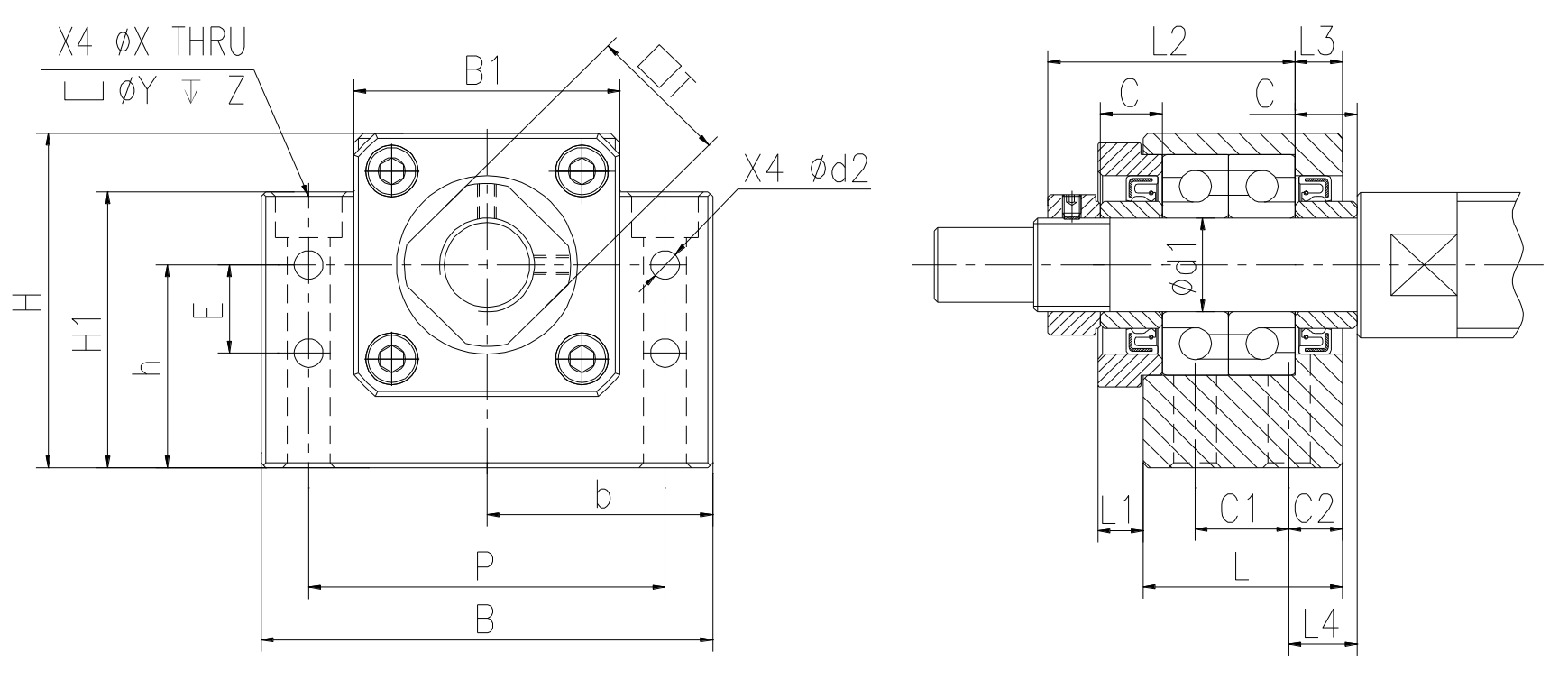
| Shaft-end radial runout | Base on a stable datum; probe perpendicular to the specified motor-end cylinder | Slowly rotate one full turn and capture high/low stable readings | Total indicated change, diameter, axial point and coupling state | Shaft drawing or approved limit |
| Fixed-end axial clearance | Probe parallel to the screw axis at the shaft end | Prevent rotation and reverse a controlled gentle axial load | Loading method, readings, repeats and instrument resolution | Support configuration, axis drawing or project spec |
| Screw-to-guide alignment | Reference the approved guide datum and fixture | Measure horizontal and vertical directions at defined travel stations | Start, stations, end, travel and maximum change | Machine drawing or accuracy spec |
| Full-stroke smoothness | Manual rotation or low-speed jog, with current and sound observation | Travel both directions, concentrating on ends and reversals | Binding point, direction difference, current or torque change | Approved function standard and baseline |
Runout is not parallelism: radial runout is the one-revolution shaft-end change relative to its support axis; parallelism is the centerline-to-guide relationship over travel.
05 / Staged trial operation
Do not start at target speed—use stages to expose problems safely
| Stage | Operation | Observe and record | Advance condition |
|---|---|---|---|
| Before power | Manual movement through full travel | Interference, binding, lubrication, guards, marks and limits | Continuous motion and completed safety checks |
| Low-speed no-load | Reciprocate in both directions | Fixed/support/ambient temperatures, current, sound and vibration | No jump, local bind or worsening trend |
| Intermediate cycle | Increase speed and cycle rate under controlled load | Same points at fixed intervals; compare directions | Temperature and current are explainable and converge |
| Target condition | Approved speed, acceleration, load and duty | Peak, stable value, stabilization time, vibration and positioning | Project limits met and cycles repeat |
| Cool-down recheck | Cool as planned and repeat critical checks | Runout, clearance, marks and hot/cold differences | No permanent shift or loosening |
Expected trend
Temperature may rise initially and then approach a stable region. Repeated identical cycles should produce comparable curve shapes and ranges.
Pause and investigate
Temperature accelerates, current jumps after tightening, direction differences expand, periodic noise/vibration appears, or a manufacturer/project limit is exceeded.
No universal temperature is specified: limits depend on bearing, grease, seal, speed, preload, environment and point. Record absolute temperature, rise above ambient and time trend.
06 / Acceptance record
Retain pre-final, final and post-run data
| Record area | Recommended fields |
|---|---|
| Machine and documents | Project, machine, axis, drawing/revision, FAT/SAT spec, date, inspector and approver |
| Products | Complete screw, fixed/support unit, locknut, coupling and motor model numbers |
| Instruments | ID, resolution, calibration due date, fixture and point photographs |
| Geometry | Three-stage runout, clearance, horizontal/vertical alignment and full-stroke results |
| Operation | Time, speed, acceleration, load, stroke, cycle, temperatures, current, vibration and noise |
| Corrective action | Event, stop condition, adjustment, recheck, owner and closure |
Mandatory limits pass, trends stabilize and post-cool-down checks do not shift abnormally.
Numbers pass but load, trend window or repeat record is incomplete; list actions and owners.
An approved limit is exceeded, binding persists, temperature accelerates or final tightening degrades the result.
07 / Common mistakes
Six habits make acceptance data unusable
Smooth hand rotation does not prove runout, clearance or alignment.
Their points, physical meaning and corrections differ.
Assembly stress returns as current, heat, noise and life loss.
Without ambient, time, speed, load and point, one number has no trend context.
Hot cycling can reveal preload, alignment, lubrication and compensation issues.
Locknuts, housing bolts and setscrews must follow the applicable process.
08 / Quick answers
Support-unit acceptance FAQ
Where should runout be measured?
Use the motor-end cylindrical surface specified by the shaft drawing or test spec; record diameter, distance from the face and coupling state.
Must a “zero-clearance” fixed end read exactly zero on the machine?
No. Machine readings also include instrument resolution, loading method, connections and other axis components. Use the approved axis limit and method.
Can further tightening correct alignment?
No. Release joints, inspect datums, center height, holes, the nut bracket and both housings, then apply approved shimming, machining or realignment.
Does temperature rise prove bearing failure?
Not alone. Environment, speed, preload, lubrication, sealing, load and point matter. Check stabilization, repeatability and correlated current/vibration.
Why perform SAT after FAT?
Transport, lifting, leveling, reassembly, coupling alignment, environment and real load can change the axis. SAT confirms the factory result at site.