Published:2026-08-28 09:00:00
Ball-screw support-unit families
The letters define mounting architecture—not a performance ranking
BK/BF, EK/EF, FK/FF, AK/AF and LK/LF are not low-to-high grades. They first define fixed/support roles, housing shape, mounting direction, center height, bolt access and shaft-end interfaces.
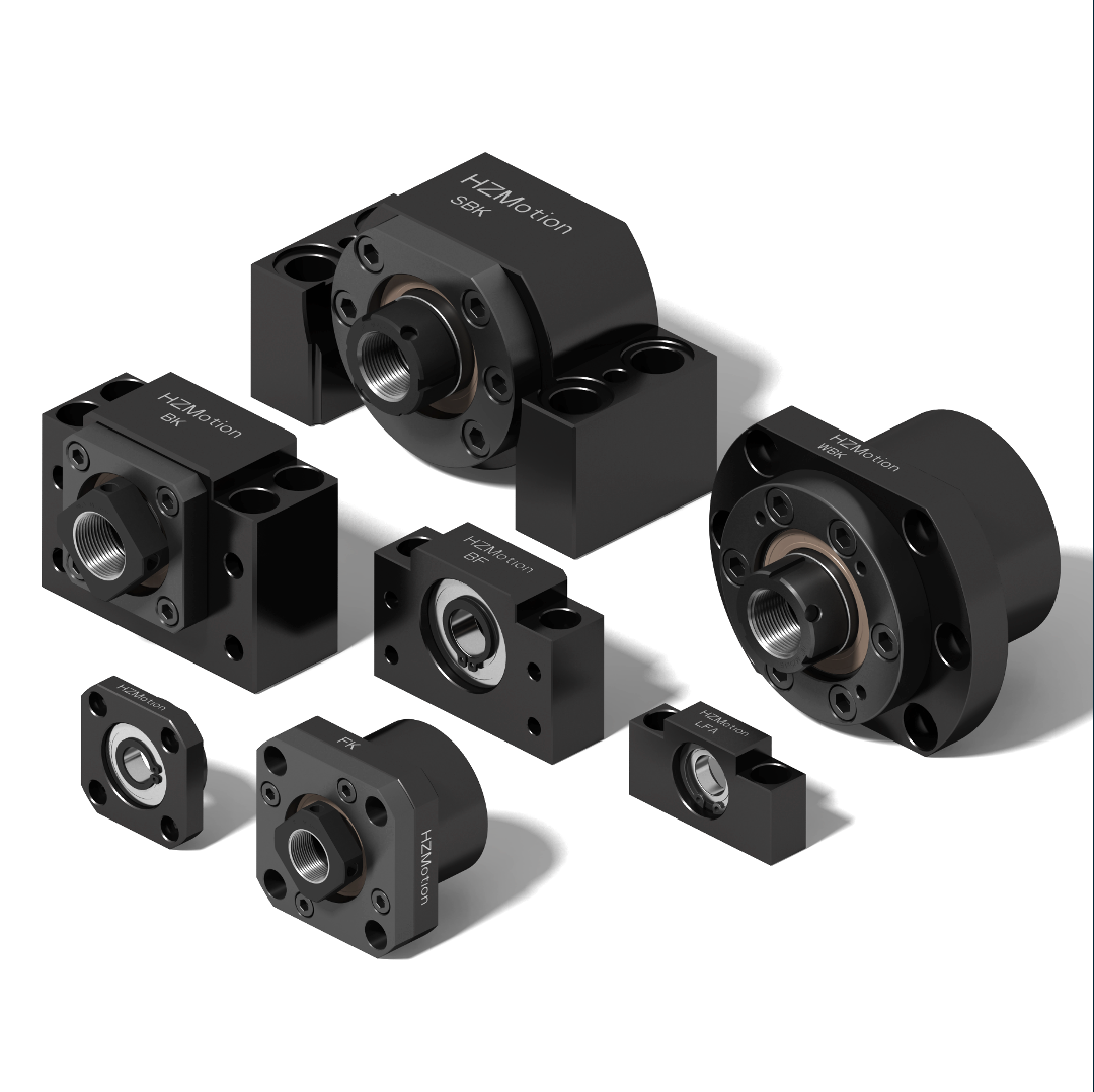
01 / Function first
The supported end is not a lower-cost substitute for the fixed end
Fixed end: axial and radial datum
A standard fixed end normally uses a paired angular-contact bearing set that is factory preload-adjusted and grease filled. It locates the screw axially, supports it radially and becomes an important installation datum.
Supported end: primarily radial support
A standard supported end normally uses a deep-groove bearing and snap ring. It does not provide the same preload or axial-location function. Thermal accommodation still depends on the fits, housing and full support architecture.
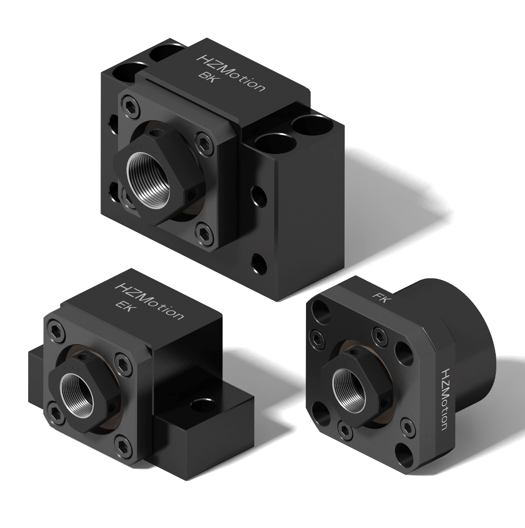
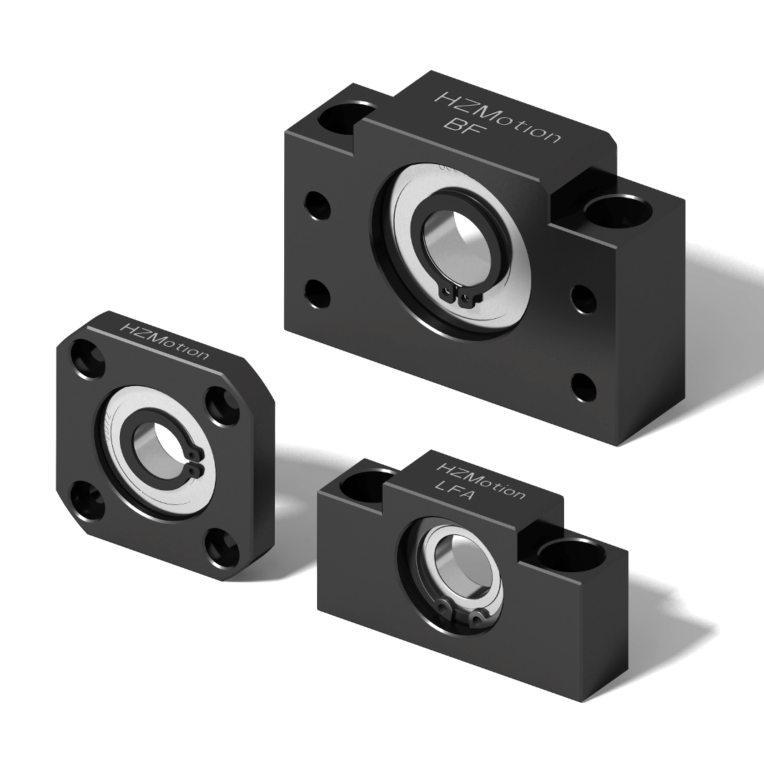
For fixed-supported, fixed-fixed and heavy-duty architecture, first read Fixed End, Support End or Heavy-Duty Fixed End? This guide continues with family geometry.
02 / Family comparison
Filter by mounting face and envelope before choosing bearing configuration
| Fixed-end family | Typical supported end | Mounting orientation | Current HZMotion range | Typical envelope consideration |
|---|---|---|---|---|
| EK | EF | Flange face parallel to screw axis | Shaft journal 5–25 mm; screw diameter 6–32 mm | Lower shoulder, compact small/medium sizes |
| BK | BF | Parallel or perpendicular mounting | Shaft journal 10–50 mm; screw diameter 10–63 mm | Four-hole block with a narrow mounting shoulder |
| FK / FKA | FF | Flange face perpendicular to screw axis | Shaft journal 6–30 mm; screw diameter 6–40 mm | Round flange for end-face or bore location |
| AK | AF | Flange face parallel to screw axis | Shaft journal 10–25 mm; screw diameter 8–32 mm | Horizontal base with countersunk mounting holes |
| LK | LF / LFA | Flange face parallel to screw axis | Shaft journal 6–25 mm; screw diameter 8–32 mm | Usually less space below the screw centerline than AK |
Range note: these are family-level filters from the current website, not a promise that every model covers the complete range. The latest model and shaft-end drawings govern.
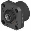
03 / Mounting geometry
“It fits” includes orientation, center height, shoulder and tool access
Confirm bolt insertion, whether the datum is parallel or perpendicular to the screw, and whether tools and gauges can reach the assembly.
The fixed end, supported end, nut bracket and guide datum must share one coordinate system. Forced tightening is not an alignment method.
Include housing width, shoulder, locknut, coupling and motor bracket. LK, AK and EK differences become important in compact machines.
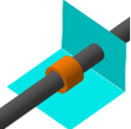
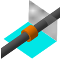
THK installation guidance also treats shim adjustment for block housings, bore location for round housings, shaft-end runout and axial-clearance checks separately. Family geometry changes both installation and realignment.
04 / Shaft end and size code
The “15” in BK15 is a nominal bearing/journal interface size—not automatically a 15 mm ball screw
Ball screws with the same nominal diameter may use different fixed journals, supported journals, threads and shoulders. One support-unit size can also cover more than one nominal screw diameter. The size code is a filter; the shaft-end drawing is the decision document.
A practical trap: in the current HZMotion standard drawings, BK10 has a 10 mm fixed-end bearing seat while the commonly paired BF10 uses an 8 mm supported journal. AK10/AF10, EK10/EF10 and FK10/FF10 show the same 10 mm versus 8 mm relationship. A matching “10” identifies a standard family pairing; it does not mean identical journal diameters at both ends.
| Fixed end | Supported end | Housing and machine |
|---|---|---|
| Bearing-seat diameter and tolerance | Supported journal and tolerance | Center height and datum surfaces |
| Shoulder, effective length and fillet | Snap-ring groove location and width | Bolt pitch, counterbores and flange diameter |
| Locknut thread, hand and length | Shaft-end length and assembly allowance | Locknut, coupling and service access |
| Seal and mating surface | Axial condition in the housing | Coaxiality with nut bracket and guides |
Cross-brand replacement: a similar BK15 or FK20 outline does not prove equal bearings, preload, datum tolerances, accessories or shaft-end geometry.
05 / Five-step selection
From support architecture to a complete part number
- Define the support arrangementFixed-supported, fixed-fixed or cantilever; calculate load, critical speed, thermal behavior and rigidity first.
- Choose the mounting familyFilter BK, EK, FK, AK or LK by mounting direction, center height, envelope, bolt pattern and assembly method.
- Pair fixed and supported endsBK/BF, EK/EF, FK/FF, AK/AF and LK/LF(LFA) are common pairs, but verify each shaft end separately.
- Check both drawingsConfirm journals, shoulders, threads, snap-ring groove, effective lengths, datums and tightening access.
- Select internal configurationUse axial load, speed, life, temperature and accuracy to select standard, TAC, economy and the required bearing class/preload.
06 / Common mistakes
Correct family selection can still fail through installation detail
Nominal screw diameter is not the fixed journal diameter.
A deep-groove supported end does not provide the same axial location or preload.
This turns alignment error into load, heat, noise and reduced life.
The locknut, snap ring, coupling and gauges all need working space.
Internal bearings, preload, housing tolerances and accessories may differ.
07 / Quick answers
Support-unit family questions
What is the main difference between BK/BF and EK/EF?
Housing geometry, mounting interface, size coverage and envelope come first. BK is a general four-hole block, while EK has a lower shoulder and focuses on smaller/medium interfaces. Internal configuration remains model-specific.
When is FK/FF the natural choice?
When the machine uses a round flange and an end-face or bore datum perpendicular to the screw axis.
How do AK and LK differ?
Both are horizontal parallel-mount families. Relative to the screw centerline, LK generally requires less space below the axis; compare bolt pattern, shoulder and shaft end as well.
Must fixed- and supported-end size numbers match?
Do not decide from the number alone. Families have common pairings, but the two machined shaft ends need separate drawing checks.
Does every supported end freely absorb thermal expansion?
Not from the name alone. A supported end is mainly a radial support; axial accommodation depends on the bearing, snap ring, fits and housing design.