Published:2026-10-10 12:00:00
Precision locknuts · Assembly and maintenance
Repeated tightening needs a diagnosis, not another turn
If a shaft-end assembly develops axial play, tightening the main nut again may leave the cause unresolved. If starting torque increases after the locking screws are secured, that does not prove a better assembly. Separate axial clamping, locking and final verification to identify where the state changes.
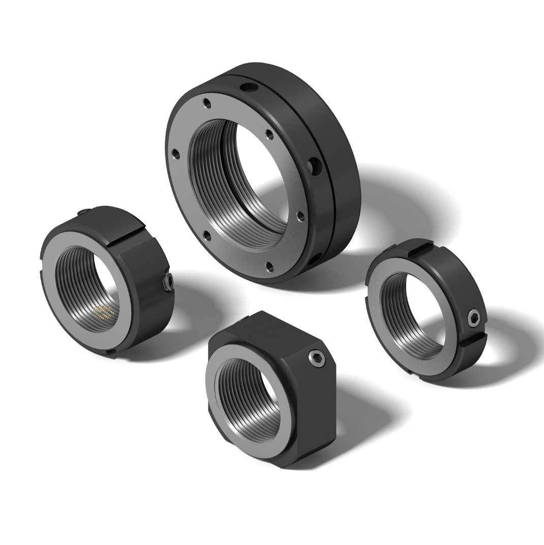
01 / Two tightening actions
The main nut clamps; the locking mechanism secures its state
Turning the main nut advances it along the shaft thread until it clamps the specified component faces. Operating its locking screws or bolts is a separate action. Follow the specified assembly sequence: the locking mechanism must not substitute for incomplete seating or axial clamping.
| Action or measurement | What it concerns | What it does not establish |
|---|---|---|
| Main-nut tightening | The main thread, seating face and specified clamped parts, such as bearing inner rings and spacers. | Wrench input torque is not axial clamping force and cannot be equated directly with bearing preload. |
| Secondary locking | The correct locking screws or bolts, access direction, sequence and specified torque. | Correctly secured locking screws do not prove that the main nut is seated correctly. |
| Starting-torque measurement | The torque needed to initiate rotation of the defined assembly from rest. | A higher reading does not prove more reliable clamping or directly establish preload. |
| Running-resistance measurement | Resistance torque at a defined speed, direction, temperature and connection state. | It is not interchangeable with a starting-torque reading taken under different conditions. |
HZMotion NRA and NR use radial locking, NF uses the illustrated 30-degree offset locking arrangement, and NK uses axial locking. These directions describe access to the locking mechanism. All four still use the main thread for axial clamping.
Before using a catalog value labelled “maximum tightening torque,” identify the fastener it applies to, whether it is a limit or an assembly setting, and the applicable thread and lubrication conditions. An unspecified value must not become a shop-floor torque instruction.
02 / Symptom checks
Nut rotation and a change in axial position are different observations
Increased axial play after operation does not necessarily mean that the main nut has rotated loose. Seating changes or an incorrect spacer and bearing stack can also affect axial position. Record witness marks between the nut and shaft, then combine them with seating and axial measurements.
| Observation | Check first | Evidence to collect |
|---|---|---|
| Nut-to-shaft witness marks have shifted | Completion of locking, fastener damage, tool access and changes in operating conditions. | Photograph the shift and review assembly records before deciding on reassembly or replacement. |
| Axial play increases without visible mark movement | Seating faces, clamped-part order, spacers, bearings and shaft shoulders. | Measure axial displacement against a defined datum and examine the clamped stack. Unchanged marks do not prove unchanged clamp force. |
| The nut binds before reaching its seat | Diameter, pitch, thread hand, damage, debris and interference near the thread runout. | Verify the complete thread specification and binding location. Do not force it with a longer wrench. |
| Starting torque increases after main-nut tightening | Bearing arrangement, clamping requirements, spacers and contact with seals or stationary parts. | Compare measurements across that stage. Both inadequate clamping and excessive constraint need assessment against the assembly requirements. |
| Rotational resistance increases after secondary locking | Locking-screw torque, sequence, seating and possible component deformation. | Locate the change during a controlled inspection. This observation alone does not establish a defective locknut series. |
| Cold checks pass, but the problem returns in operation | Temperature, lubrication, load, vibration and shaft-support alignment. | Record temperature, elapsed running time and operating conditions; inspect the complete support assembly. |
Witness marks need a clear reference, photographs and a date. They are supplementary evidence of relative movement, not a measurement of clamp force or a replacement for axial and running checks.
03 / Threads and seating
Make sure tightening acts on the intended interfaces
Specify more than the nominal thread diameter
Check diameter, pitch, thread hand and fit requirements. Also verify usable shaft-thread length, runout location and the final nut position. M20×1.0 and M20×1.5 are not interchangeable. Engagement over a few turns is not proof of compatibility; stop if abnormal resistance appears before seating.
The nut face must contact the specified load-bearing face
Check the relationship between the shaft shoulder, bearing inner ring and spacer. Chamfers, fillets, burrs, impact damage or trapped debris can cause early or partial contact. Confirm that the nut does not bottom against the thread runout, a seal, an outer ring or the housing where that contact is not intended. A visually closed gap is not sufficient evidence of correct seating.
Every locking position must remain accessible
Check that the specified tool can fully engage each locking screw without obstruction from a coupling, guard or adjacent component. Do not drive a screw with a mismatched bit at an unintended angle. Replacement screws must match the specified thread, length, end form and other required properties.


For a series comparison, see the NRA, NR, NF and NK interface selection guide. Cleaning, lubrication and any locking compound must follow the specified procedure. Changing thread friction conditions means the same torque cannot simply be assumed to produce the same clamping state.
04 / Inspection sequence
Preserve the stage at which the condition changes
- Stop and record the initial stateIsolate unintended motion and independently support vertical axes and external loads. Record the model, marks, axial condition, temperature and symptoms before disturbing the assembly.
- Find both tightening requirementsIdentify the separate main-nut and locking-fastener instructions, including tools, sequence, torque and lubrication. Resolve any unclear fastener reference or model applicability with engineering.
- Inspect the thread and clamped stackFollow the specified disassembly method. Release the locking mechanism as required and verify release before turning the main nut. Stop if it binds. Inspect shoulders, faces, spacers, the bearing arrangement and damage.
- Establish main-nut clampingSeat the intended faces with the specified tool and follow the bearing and support assembly requirements. Check axial and rotational state by the permitted method; do not arbitrarily increase preload.
- Complete locking and record changesApply the model-specific sequence and torque at every required locking position. Confirm tool engagement, completion and nut position. Investigate any abnormal change before continuing.
- Verify the completed assemblyAfter all fastening is complete, check axial displacement, starting torque and running resistance. Restore guards, then perform the required low-speed, load and warm-running checks under the commissioning procedure.
Intermediate checks must use an approved static or manual method. Do not power an assembly with incomplete locking, loose connections or inadequate support, and do not force rotation through a hard spot.
05 / Acceptance records
Keep clamping and locking evidence in the same record
| Record item | Include | Purpose |
|---|---|---|
| Product and references | Full series, main thread, shaft and bearing assembly identification, drawing and procedure revisions. | Match instructions to the installed configuration. |
| Contact relationship | Actual load-bearing parts, assembly order, thread and seating inspection results. | Exclude bottoming, partial contact and incorrect clamping. |
| Main-nut clamping | Specified method, settings, completion records, tool identification and thread lubrication state. | Keep main-nut inputs separate from locking-fastener inputs. |
| Locking operation | Required positions, sequence, completion at each position and any abnormality. | Identify omitted or obstructed locking operations. |
| Axial state | Datum, applied-force method, direction, measuring position, results and drawing limits. | Avoid comparing displacement under different loads or references. |
| Rotational state | Separate starting and running readings, with temperature, speed, direction and included components. | Identify changes introduced by clamping or locking. |
| Final verification | Witness-mark photographs, load and warm-running results, corrective action, inspector and date. | Support acceptance and later maintenance. |
Acceptance limits must come from the confirmed drawing and procedure. Do not transfer limits from another model or infer the original clamp force from the torque required to loosen the nut. The ball screw support-unit acceptance checklist covers related shaft-end checks.
06 / Repair decisions
Check adjacent parts before replacing the nut
- Incorrect thread specification: select the correct complete thread. Do not force assembly or improvise thread rework.
- Damaged nut, locking screw or seating face: have engineering determine the replacement scope and inspect the shaft thread and mating parts. A new nut cannot repair a damaged shaft.
- Incorrect stack, spacer or bearing arrangement: correct it using the approved procedure. Further main-nut tightening can turn the issue into excess starting torque, temperature rise or positioning error.
- Movement returns during operation: retain operating and locking records, then inspect vibration, load and alignment. Repeated retightening is not evidence that the cause has been resolved.
For work involving fixed-end bearings, consult the fixed-end support disassembly and bearing replacement guide. Send HZMotion the complete model, shaft-end drawing, assembly photographs and the stage at which the condition changed.
07 / FAQ
Frequently asked questions
Can the main nut and locking screws use the same torque?
Do not assume so. Their sizes, functions and load paths differ. Identify the separate requirements before assembly.
Is there one universal locknut tightening torque?
No. Series, size, thread condition, clamped components and assembly conditions all matter. Use the corresponding drawing and procedure.
Do unchanged witness marks prove that the assembly is sound?
No. They do not exclude seating changes or altered axial condition. Check axial movement and operating results as well.
Does increased starting torque mean improved preload?
Not necessarily. Excess constraint, incorrect contact or interference may also cause it. Locate the assembly stage that changed and apply the specified preload and acceptance method.
Will a new nut solve repeated loosening?
Only if the cause and replacement scope have been established. Inspect shaft threads, seating, the clamped stack and locking execution, then verify the repair.