Published:2026-10-10 12:00:00
Precision locknuts · Series selection
Check tool access, then verify the complete interface
NRA, NR, NF and NK differ in more than body shape. Radial, 30-degree offset and axial locking change tool access, assembly order and service clearance. A suitable nut must fit, clamp the correct faces, allow every locking operation and remain removable.
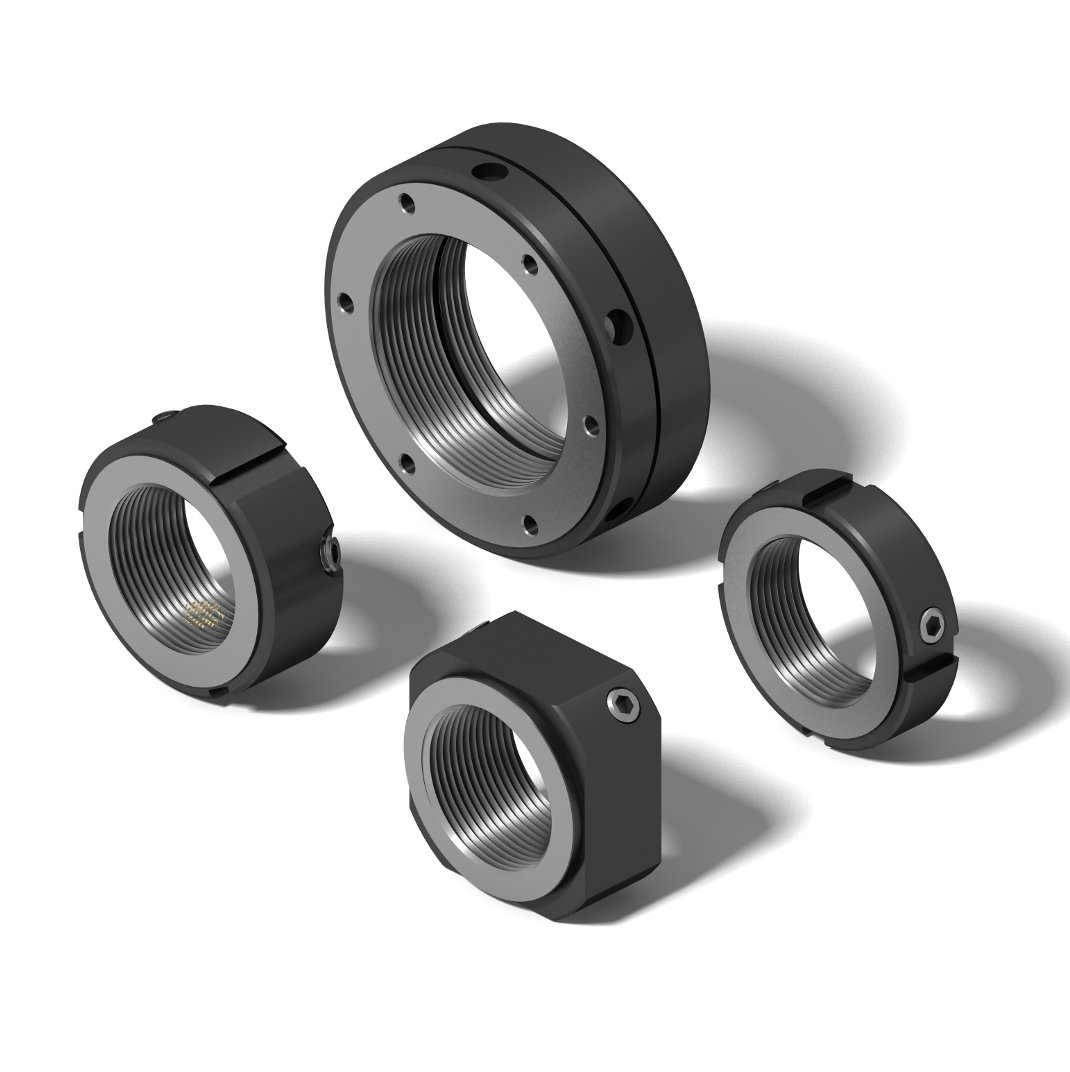
01 / Series comparison
Locking direction describes access, not the direction of clamping force
The main nut advances along the shaft thread and clamps the specified component faces. Radial, offset and axial refer to the subsequent locking operation. They do not mean that one series carries only radial force while another alone provides axial clamping. HZMotion groups NRA and NR as standard locknuts and NF and NK as heavy-duty locknuts; suitability still requires assessment of the actual size and complete assembly.


| Series | Secondary locking access | Clearance priorities | Common omission |
|---|---|---|---|
| NRA | Radial. | Side access to every locking position and main-nut wrench clearance. | The overall profile and width across flats are different checks; one dimension does not define the entire envelope. |
| NR | Radial. | Circumferential obstructions, locking positions, wrench engagement and operating sweep. | A nut fitting inside a recess does not prove that a tool can reach it. |
| NF | The illustrated 30-degree offset direction. | A continuous inclined path along the locking-screw axis, clear of side and end obstructions. | A radial gap alone is insufficient; an arbitrary tool angle cannot replace the specified access direction. |
| NK | Axial. | End clearance for insertion, including access after fitting couplings and covers. | A visible end face does not guarantee enough length to insert the tool and apply torque correctly. |
Check main-nut installation, tightening and removal separately for every series. Locking-screw access does not provide main-nut wrench clearance or establish bearing preload or machine load capacity.
02 / Six interfaces
A matching thread is only the first check
- Complete main threadVerify nominal diameter, pitch, thread hand and fit requirements. Shaft diameter, nominal thread diameter and support-unit size are not interchangeable identifiers.
- Usable engagement and final positionCheck usable thread length, relief, shaft shoulder and installed nut position. Achieve the specified engagement without premature binding at the thread runout.
- Load-bearing faceIdentify the intended bearing inner ring, spacer or other clamped part. Check the contact annulus, chamfers and fillets; exclude unintended contact with seals or the housing.
- Body envelopeUse the specific drawing to check D, h, applicable flats, steps and other features. Provide the design clearances required for tolerances and adjacent moving parts.
- Tools for both tightening actionsCheck main-nut wrench engagement and operation separately from locking-tool insertion and operation. Include every required locking position.
- Assembly and service pathsDefine the order of fitting couplings, guards and covers, and what must be removed to release locking, unscrew the nut and withdraw it from the shaft.
After these interface checks, engineering must assess the clamped components, load direction, vibration, temperature and support arrangement. Catalog load ratings have defined conditions; they are not direct substitutes for bearing preload or the dynamic capacity of the complete machine.
03 / M20 dimensional example
The same M20×1.0 thread comes with different body dimensions
The following dimensions are taken from the corresponding HZMotion catalog entries. Units are mm. Read D according to each series drawing: NRA is not a complete cylindrical body, so D alone does not describe its entire profile. Dimension h is body thickness; it excludes tool insertion, operation and removal clearance.
| Series and main thread | Drawing dimension D | Body thickness h | Locking access |
|---|---|---|---|
| NRA · M20×1.0 | 35 | 11 | Radial |
| NR · M20×1.0 | 32 | 10 | Radial |
| NF · M20×1.0 | 38 | 16 | 30-degree offset |
| NK · M20×1.0 | 40 | 18 | Axial |
For example, an assembly providing body space for NR at D=32 and h=10 cannot automatically accept NK merely because it is also available with an M20×1.0 thread. NK has D=40 and h=18 in this example, and its end tool path and seating relationship must also be checked. Conversely, a smaller body does not establish that NR can serve every application originally designed for NF or NK.
The NR, NF and NK catalog tables also include M20×1.5 versions. The same nominal M20 diameter does not mean the same pitch. Purchasing documents should state the complete thread and include a confirmed drawing.
This example illustrates the comparison method; it is not an interchangeability recommendation. Final selection requires the drawing for the supplied part and all thread, seating, tool and machine checks.
04 / Tool and service clearance
Include the tools in the assembly drawing


Open side access with a restricted shaft end
NRA or NR may be candidates if their interfaces and application requirements match. Check the circumferential location of every locking position: clearance on one side does not establish access on the other. Include the nut's angular position after axial clamping rather than assuming that a screw will align with a service opening.
Restricted side access with an open shaft end
NK may be a candidate because its locking operation is accessed axially. Place the actual tool head, extension and torque-tool envelope into the assembly. Check covers, couplings, shaft projection and all locking positions. Main-nut wrench access and withdrawal still need separate checks.
An available inclined corridor
NF needs a continuous tool path along the illustrated 30-degree offset direction, involving both side and end clearance. A rendering alone cannot establish access. Do not compensate for insufficient clearance by driving the screw at an unintended angle.
Installation access is not the complete service plan
If the nut must be installed before a coupling or cover, record the inspection stages and disassembly order. A service review should cover releasing the locking mechanism, unscrewing and withdrawing the main nut, and introducing measuring tools. Removing adjacent parts may be acceptable, but that requirement should be confirmed during design.
05 / Selection sequence
Start with the shaft end and assembly conditions
- Define the clamped components and operating conditionsProvide the bearings, spacers, shoulders and support arrangement, together with load, speed, temperature, vibration and orientation. Engineering should confirm the required clamping conditions.
- Confirm the complete threadRead diameter, pitch, hand, fit and usable length from the shaft drawing, then exclude incompatible sizes.
- Screen by locking access directionCheck radial, illustrated offset and axial tool paths separately. Retain only candidates that allow the prescribed operation.
- Check dimensions and contact facesCompare the actual body, seating face, chamfers and adjacent parts. An identical main thread alone does not justify a series substitution.
- Confirm fastening and maintenanceIdentify separate tools, sequence and torque references for the main nut and locking mechanism. Confirm final inspection access and document removal.
- Validate the sample assemblyFollow the confirmed procedure to check seating, axial state, starting torque and operating conditions. Archive the final part identification, drawing and results together.
If starting torque or rotational resistance increases during assembly, use the locknut thread, seating and locking troubleshooting guide to identify the stage involved. Do not relax fastening requirements to accommodate an incorrect interface.
06 / RFQ and purchasing
Turn “an M20 locknut” into a verifiable requirement
| Item | Information to provide | Why it matters |
|---|---|---|
| Series and size | NRA / NR / NF / NK, complete main thread, quantity and confirmed supply drawing. | Avoid ordering by shaft diameter or an incomplete designation. |
| Shaft end and clamped parts | Shaft drawing, shoulder, relief, seating faces, bearings and spacers. | Check engagement, contact and axial dimensions. |
| Available space | Body envelope, adjacent parts, main-nut and locking-tool access directions. | Verify both fit and correct tightening access. |
| Operating requirements | Load, speed, temperature, vibration, orientation and machine acceptance criteria. | Avoid substituting a product category for application assessment. |
| Assembly and service | Tools, assembly order, inspection stages, removal path and replacement conditions. | Keep service conditions consistent with the selection. |
For a replacement, also provide the existing part's full identification, measured dimensions and original drawing. A photograph or an approximate outside diameter cannot establish thread, seating and locking compatibility.
07 / FAQ
Frequently asked questions
Does radial locking mean the nut only carries radial force?
No. It describes access to the locking mechanism. The main thread and face still provide axial clamping; capacity and preload requirements must be checked for the actual assembly.
Can all M20 versions be exchanged between the four series?
No. Verify pitch, hand and fit, then body dimensions, seating, tool paths and application requirements. Even identical complete threads do not establish interchangeability.
Is heavy-duty NK always the better choice?
No. Interfaces, body size, end clearance and service access may rule it out. The specific part and complete assembly must meet the intended conditions.
Does NF allow the tool to be tilted to any convenient angle?
No. The 30-degree designation corresponds to the locking-screw direction shown on the drawing. Use the specified tool engagement and access path.
Why might a nut be impossible to install even if its body fits?
The main-nut wrench, locking tools, insertion and removal paths, seating operation and measurement access also require space. Check tools and adjacent components in the assembly drawing.