Published:2026-11-10 00:00:00
Updated:
Lead · Drive · Duty matching
Connect travel per revolution to the complete axis
Lead links linear speed to rotational speed and axial force to torque. Comparing practical leads against one duty makes those trade-offs clear, while showing what the motor and the rest of the axis still need to deliver.
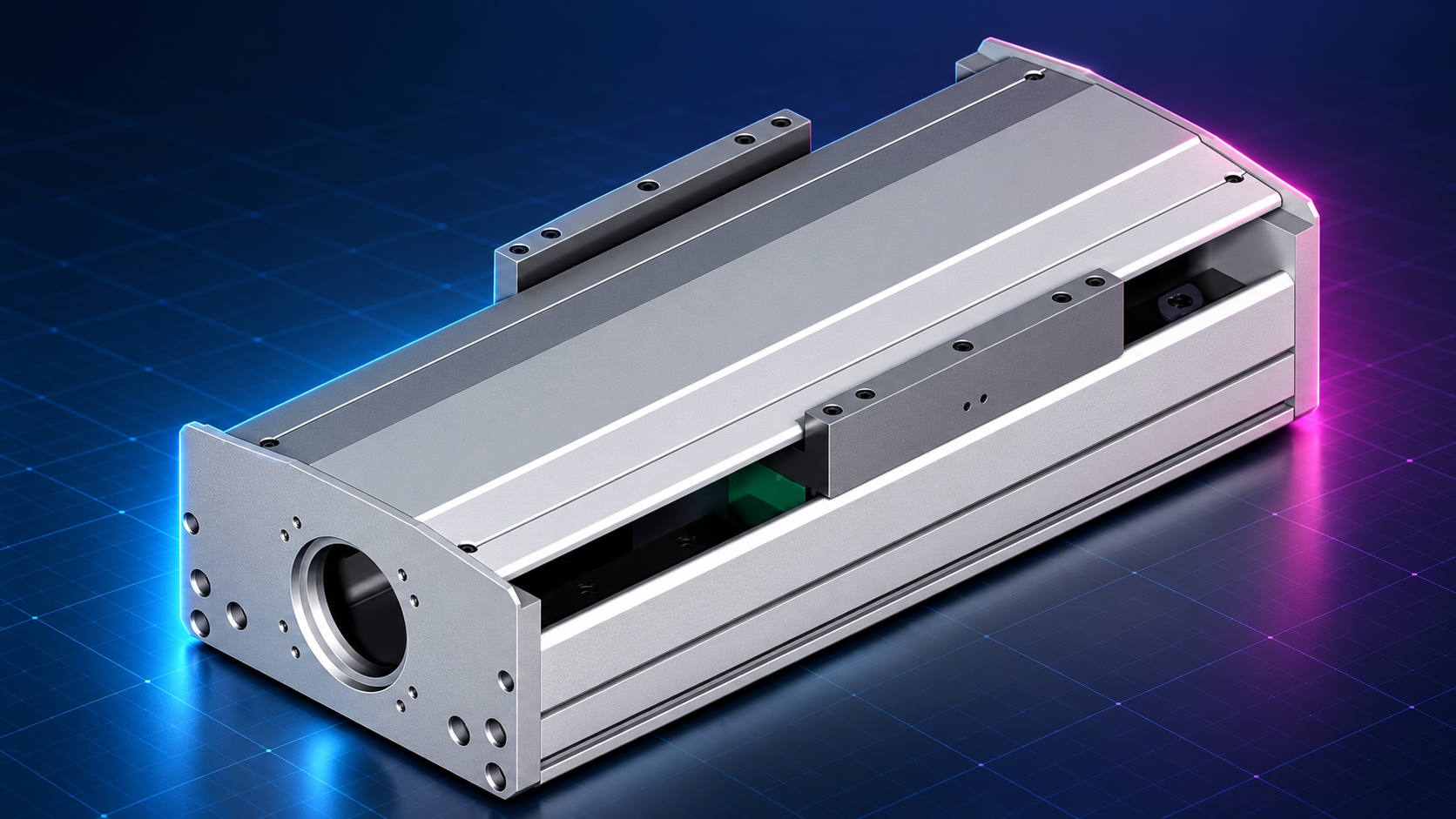
01 / Design inputs
Compare leads against the same motion task
A lead is often chosen early in an axis design: a small lead for a short, precise move, or a large lead for a fast transfer. That can be a useful starting point, but it is not yet a complete selection. Lead changes screw speed, force-related torque and the inertia of a translating mass as seen at the rotating shaft. A practical comparison keeps those effects together.
Lead p is the theoretical axial travel produced by one relative revolution between the screw and nut. This article assumes direct drive, with the motor and screw turning at the same speed and the nut prevented from rotating. A gearbox or rotating-nut design needs its own speed relationship. For a multi-start thread, lead and the spacing between adjacent threads are different quantities.
| Input | What to specify | Why it matters |
|---|---|---|
| Motion task | Working stroke, move time, dwells and complete velocity profile | Use actual peak speed; distance divided by time gives only average speed |
| Moving mass | Carriage, tooling, workpiece and moving accessories | Determines acceleration force and reflected translating inertia |
| Axial forces | Process force, guide resistance and gravity along travel | Separate steady travel, acceleration, deceleration and holding |
| Motor and drive | Torque–speed envelope, peak duration, supply and feedback | Check the calculated point against the available operating region |
| Positioning target | Position error, repeatability, command increment and settling time | A resolution value does not define complete axis acceptance |
Keep load, cycle and evaluation position unchanged while comparing leads. If a large-lead proposal quietly reduces acceleration while the small-lead proposal retains the original cycle, the difference in motor requirements cannot be attributed to lead alone. Record every changed assumption before comparing the results.
The peak speed may be much higher than the average on a short move. Likewise, the largest force can occur during acceleration or a process step rather than at maximum speed. Retaining the time history makes it possible to check the combinations that actually occur, instead of combining unrelated maximum values into a fictitious operating point.
02 / Parameter relationships
Four quantities answer four different questions
n = 60v / p; TF = Fpm / (2πη)
n in rpm; v in mm/s; p in mm/rev; p_m = p/1000 in m/rev; F in N; T_F in N·m. η is the efficiency for the stated driving direction.The first expression gives the required screw speed. The second gives the torque term associated with an axial force when the motor drives the load through the screw. Efficiency is in the denominator because input power must also supply the losses. Do not use this expression unchanged to calculate the torque produced when a load backdrives the motor; that direction needs the appropriate backdriving relationship.
Jmass = m[pm/(2π)]²; Δxcmd = p / Ncmd
m in kg; J_mass in kg·m². N_cmd is the effective number of command units per screw revolution; Δx_cmd is in mm per command unit.| Relationship | Effect of increasing lead | Companion check |
|---|---|---|
| Speed n ∝ 1/p | Lower rpm at the same linear speed | Screw, bearing, coupling and motor speed limits still apply |
| Force torque T_F ∝ p | More torque for the same axial force | This term is not the complete acceleration or friction torque |
| Translating inertia J_mass ∝ p² | Greater reflected inertia of the moving mass | Add screw, coupling and other rotating inertias separately |
| Command increment Δx_cmd ∝ p | Larger travel per command unit at the same unit count | This is not positioning accuracy or guaranteed minimum physical motion |
J_mass follows from the motion relationship and equivalent kinetic energy; its definition does not contain efficiency. Account for drive losses separately when calculating torque. Some sizing tools incorporate losses into an equivalent parameter, so follow that tool’s definitions rather than applying the same loss allowance again. N_cmd also depends on command mode, electronic gearing and unit scaling; it is not necessarily the encoder’s advertised count.
Lead changes rotational acceleration as well. For direct drive, α = 2πa/p_m, with linear acceleration a in m/s². A smaller lead requires greater angular acceleration for the same linear acceleration. It therefore increases the acceleration torque of the screw, coupling and motor rotor. Comparing J_mass alone cannot establish which lead needs less peak motor torque.
03 / Worked comparison
Put the speed benefit beside the torque requirement
Consider an independent horizontal-axis example: steady speed 300 mm/s, required steady axial force 600 N, moving mass 40 kg and assumed driving efficiency 0.90. The drive is direct and uses 131,072 effective command units per screw revolution. Compare hypothetical leads of 5, 10 and 20 mm. No HZMotion model is assigned to this example, and the three leads are not presented as options available on one product family.
| Lead p | Screw speed | Steady force torque T_F | J_mass / kg·m² | Command increment / μm |
|---|---|---|---|---|
| 5 mm | 3,600 rpm | 0.531 N·m | 2.533 × 10⁻⁵ | 0.0381 |
| 10 mm | 1,800 rpm | 1.061 N·m | 1.013 × 10⁻⁴ | 0.0763 |
| 20 mm | 900 rpm | 2.122 N·m | 4.053 × 10⁻⁴ | 0.1526 |

Changing from 10 to 20 mm halves the required speed, doubles steady force torque and multiplies the translating inertia by four. It can ease a high-speed constraint while moving the required operating point into a different part of the motor’s torque envelope. The 5 mm option needs less force torque but must produce it near 3,600 rpm. The actual torque–speed curve decides whether either combination is available.
Pin = TF · 2πn/60 = Fvm/η = 200 W
Here v_m = 0.300 m/s. All three leads have the same steady load power. This excludes separate preload, seal and rotational acceleration terms and is not a recommended motor power rating.The power check is a useful way to catch a calculation error. Lead redistributes the same steady mechanical duty between torque and speed; it does not make the work disappear. A full selection must include starts, acceleration, deceleration, dwell and the repeated cycle, with separate checks for peak and RMS torque.
The command increments in the final column are deliberately small. They describe a numerical mapping between commands and theoretical travel, not measured motion at the workpiece. Mechanical compliance, friction, screw lead error and feedback arrangement remain relevant even when the command increment is far below the application’s positioning tolerance.
04 / Feasibility checks
Check every candidate through the complete drive
Start with the required speed and the torque available at that speed. Screw critical speed, ball-circulation limits, support-bearing speed, coupling capability and motor limits can each constrain the design. Their definitions differ. A motor’s ability to reach a particular rpm does not establish that the complete screw axis can operate there.
During acceleration, one consistent method is to calculate F_axis = ma + F_resist, convert that axial force into screw torque, then add rotational acceleration torque J_rot α and any resistance terms not already represented by the efficiency model. In this method J_rot excludes the translating mass already included through ma. An equivalent-inertia method is also possible, but the two bookkeeping approaches must not count the same acceleration twice.
For positioning, review screw lead error, elastic displacement of the nut and supports, thermal conditions, feedback location and settling time. Electronic gearing changes the mapping of command units; it does not change mechanical lead. Finer command units do not remove mechanical error. An axis using a linear encoder still needs sufficient drive margin and a stable dynamic response.
If a reducer is added, define its ratio explicitly. With i = motor speed/screw speed, n_motor = i n_screw and the load-shaft inertia reflected to the motor is J_load/i². Account separately for transmission efficiency, its own inertia and lost motion. At fixed linear speed and screw lead, changing the ratio does not reduce the screw’s rpm, so it cannot bypass the screw critical-speed limit.
Finally, compare the intended operating regions rather than isolated catalog peaks. Peak torque may be permitted only for a limited duration, while allowable speed can depend on stroke or screw length. Record the duration, temperature assumptions and selected mechanical configuration beside the calculated values. That makes the remaining verification specific and repeatable.
Compare candidates with one load and motion profile. Acceleration, backdriving and reduction gearing each need consistent direction, efficiency and shaft-side definitions.
05 / From analysis to a model
Turn the comparison into confirmed ordering information
The HZMotion actuator catalog treats lead as part of the ordering information. For example, the HZM200 single-axis performance table lists configurations with 5 mm and 10 mm leads. This verifies options for that series; it does not establish the choices for every other model or stroke. When changing lead, recheck the selected configuration’s screw load data, usable travel and permitted speed.
Local product basis: HZMotion actuator catalog, PDF page 299, single-axis worktable performance table, and page 218, TKS ordering information. The 20 mm lead in this article is an independent example, not a supply claim for those models.
- Keep two or three candidatesStart with leads actually available for the intended model rather than assuming any numerical value can be supplied.
- Build one duty comparisonRecord peak speed, force by phase, rpm, torque and the method used to reflect inertia.
- Apply the real limitsCompare torque–speed capability, thermal duty, screw and bearing speed, stroke and installation envelope.
- Confirm the interfacesCheck motor shaft, coupling, bracket, fixed-end support and nut bracket. A lead change can also change the screw specification.
- Validate representative operationRecord load, temperature, motion profile, settling time and position error, then retain the final configuration revision.
Where data are missing, keep the conclusion conditional and useful: for example, the new lead reduces required rpm, while available torque and cycle temperature remain to be confirmed. Separating calculated quantities from missing inputs is more informative than assigning a motor power prematurely. It also gives the next design review a clear starting point.
Retain the selected lead together with the motor, drive settings, screw-end drawing and tested motion profile. A later motor or stroke change can move the same nominal assembly to a different operating region. The saved comparison should make that change visible without requiring the original selection to be reconstructed from memory.
06 / Questions
Common lead-selection decisions
Does a smaller lead always produce better accuracy?
No. It gives a smaller theoretical travel per command unit when the unit count is unchanged. Actual positioning also depends on lead error, compliance, temperature, feedback and assembly. Compare measured accuracy under the same conditions.
Can a larger lead reduce both motor speed and torque?
At the same linear speed and axial force, a larger lead reduces screw rpm but increases force-related torque. A change in gearing or duty creates a different comparison and must be evaluated explicitly.
Why is translating inertia not the whole load inertia?
It describes only the kinetic energy of translating mass reflected through the lead. The screw, coupling, transmission and other rotating parts must also be included at the correct shaft side.
What information starts a useful review?
Provide working stroke, full cycle, moving mass, process forces, mounting direction, accuracy target and motor/drive models. For an existing screw or actuator, include the complete model and shaft-end interface drawing.