Published:2026-08-09 19:10:00
Ball screw critical speed
The same screw can have very different permissible speeds under different end conditions
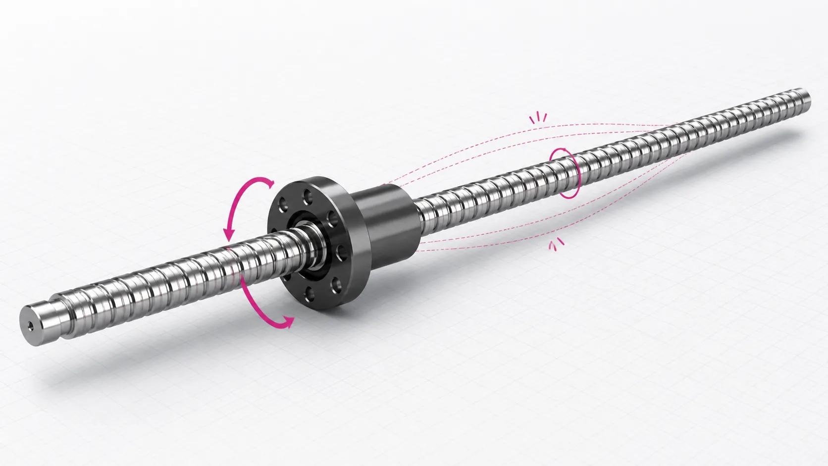
A rotating ball screw behaves like a slender shaft. As its speed approaches a bending natural frequency, the middle span can develop severe vibration or whip. Whether the ends are fixed-free, supported-supported, fixed-supported or fixed-fixed directly changes the critical-speed limit.
01 / Phenomenon and limits
Screw whip is a rotating-shaft bending resonance
A ball screw is not a perfectly straight, perfectly uniform rigid body. Manufacturing variation, assembly eccentricity, coupling error and gravity create small excitation forces. At low speed the screw can rotate steadily; close to a bending natural frequency, mid-span deflection is amplified into the oscillation commonly called whip.
Vibration appears mainly in a higher-speed band and reduces after slowing down, often with periodic noise, shaft-end runout or positioning fluctuation.
Extra bearing load, impact in the ball-nut recirculation path, coupling wear, higher temperature and loss of positioning accuracy.
Misalignment, unequal base heights, coupling eccentricity, loose locknuts and a permanently bent screw can create similar symptoms.
Do not confuse the limits: critical speed describes bending resonance of the complete screw shaft. “Maximum bearing speed” in a support-unit manual describes the capability of the installed bearing. Both must be checked separately.
02 / Calculation method
Three inputs control the critical-speed result
- N₁
- Permissible speed determined by shaft critical speed. The λ₂ factors used here already include a 0.8 safety factor.
- d₁
- Screw thread minor or root diameter in mm. Do not substitute nominal diameter; use the value for the actual screw.
- Lᵦ
- Distance between mounting faces as defined by the supplier's equation, in mm. It is not necessarily stroke or total screw length.
- λ₂
- Mounting factor: fixed-free 3.4, supported-supported 9.7, fixed-supported 15.1 and fixed-fixed 21.9.
Why is length so important?
Permissible speed is inversely proportional to Lᵦ². Increasing the support span by 1.5 times reduces the result to about 44% when the other inputs stay unchanged. Long stroke often becomes a speed constraint before load capacity does.
Do not apply the safety factor twice
The factors 3.4, 9.7, 15.1 and 21.9 used with this equation already represent the 0.8 safety margin in the published engineering method. If theoretical coefficients without that margin are used instead, multiply by 0.8 once—not again.
03 / End restraint
How four mounting arrangements change permissible speed
Fixed-free
λ₂ = 3.4One end provides axial and radial restraint while the other is cantilevered. It has the lowest critical-speed factor and generally suits only short, lower-speed or special cantilever layouts.
Supported-supported
λ₂ = 9.7Both ends provide simple radial support without the axial datum and bearing preload of a fixed end. The factor is higher than for a cantilever arrangement.
Fixed-supported
λ₂ = 15.1The most common general-purpose arrangement. The fixed end establishes axial location and carries thrust; the support end provides radial support and accommodates the system's thermal-growth strategy.
Fixed-fixed
λ₂ = 21.9Both ends provide rigid restraint, giving the highest factor and allowing controlled pre-tension. It also demands better datum accuracy, coaxiality, pre-tension control and assembly procedure.
| Support function | Typical HZMotion families | System role | Common pairing |
|---|---|---|---|
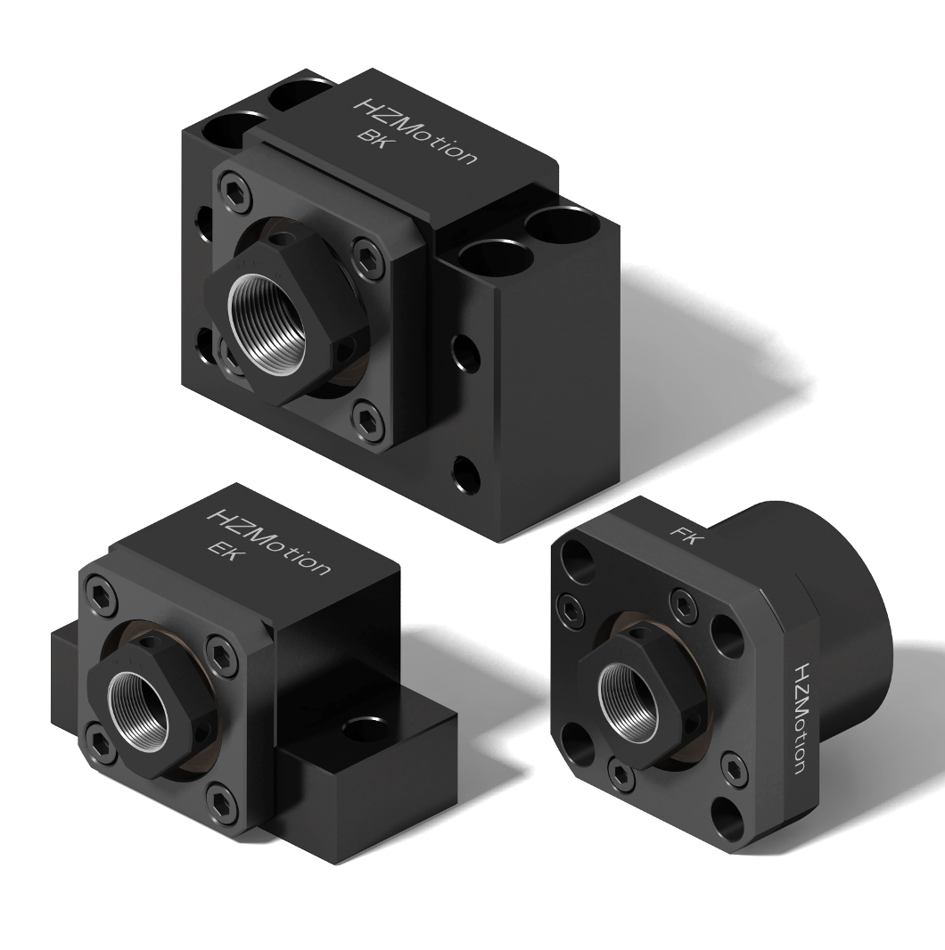
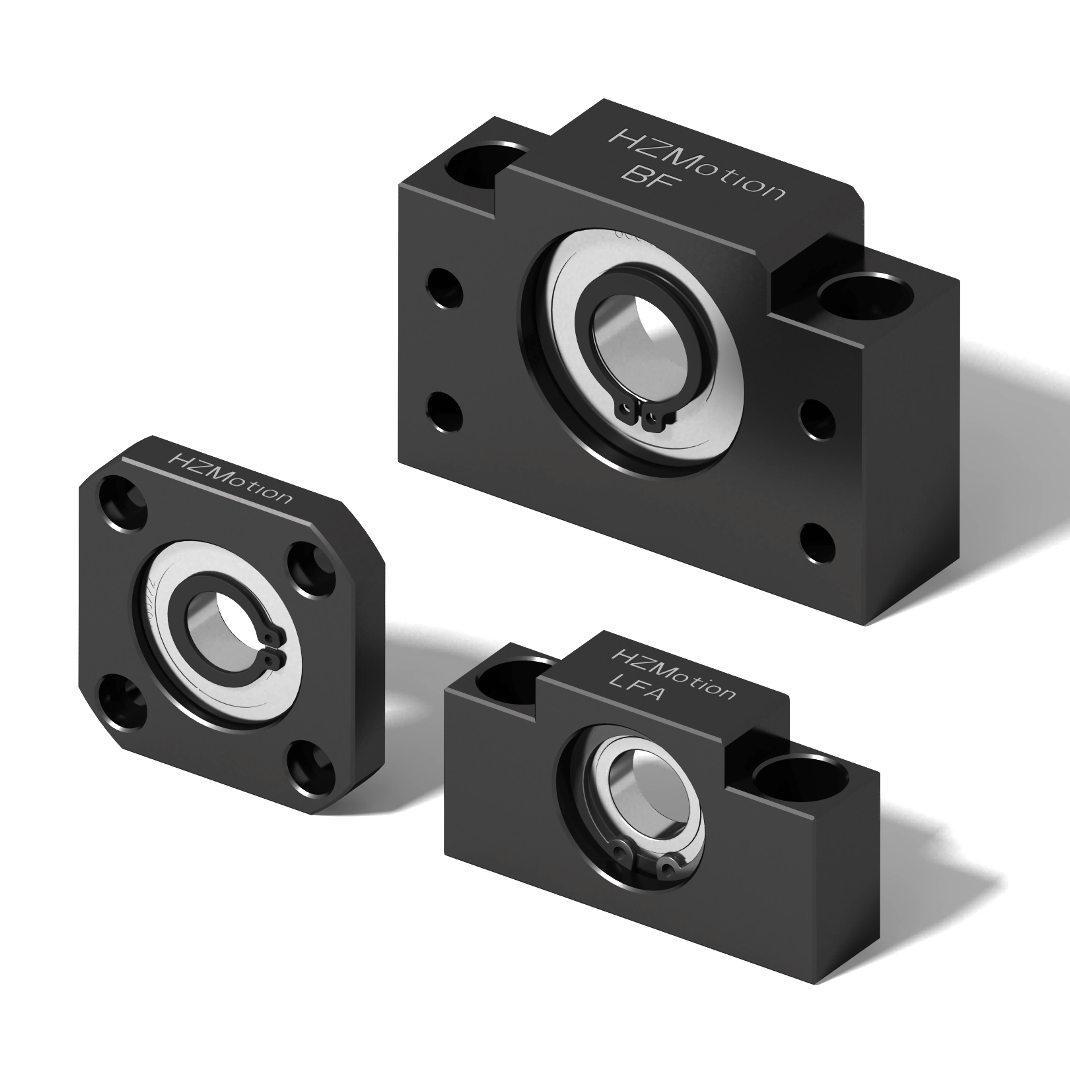
| Standard fixed end | EK, BK, FK/FKA, AK, LK | Axial location + radial support | Fixed-supported with EF, BF, FF, AF or LF/LFA |
| Standard support end | EF, BF, FF, AF, LF/LFA | Radial support within the thermal-growth strategy | Opposite a standard fixed end |
| Heavy-duty fixed end | SBK, SBK-U, WBK, FBSA, MBK | Higher axial capacity and support rigidity | Heavy-load or fixed-fixed designs subject to system calculation |
04 / Same-screw example
Minor diameter 17.5 mm and support span 1100 mm
Only λ₂ changes in the comparison below. The result isolates the effect of end restraint; a real design still needs the supplier's minor diameter, mounting-face distance and DN limit.
Reading the result: changing this example from fixed-supported to fixed-fixed raises the permissible result by about 45%, while fixed-fixed is more than six times fixed-free. The gain exists only when the real installation achieves the assumed restraint.
A larger lead reduces screw rpm at the same linear speed
- Example
- At 500 mm/s, a 10 mm lead requires 3000 rpm; a 20 mm lead requires 1500 rpm.
- Trade-off
- Increasing lead also changes resolution, drive torque, back-driving behavior and available nut designs, so it cannot be changed in isolation.
- Sequence
- Calculate operating rpm from speed and lead, then compare it with critical speed, DN, bearing and drive-system limits.
05 / Design and diagnosis
Operating speed must pass four separate limits
| Check | What it limits | Required inputs | Common error |
|---|---|---|---|
| Shaft critical speed N₁ | Long-shaft bending resonance and whip | Minor diameter, support span, end condition | Substituting nominal diameter or stroke |
| Ball screw DN limit N₂ | High-speed capability of the nut circulation system | Ball center diameter, nut design, supplier DN value | Assuming critical-speed calculation is sufficient |
| Support-bearing speed | Capability of bearings inside the support units | Bearing model, arrangement, lubrication and preload | Treating bearing maximum speed as shaft critical speed |
| Drive and machine limit | Motor, coupling, control, heat and protection | Duty cycle, acceleration, assembly accuracy, environment | Designing from a short no-load maximum only |
When the critical-speed margin is insufficient
- Confirm the actual spanUse the mounting-face distance defined by the equation; do not mix stroke, total length and unrelated drawing dimensions.
- Reduce operating rpmAdjust speed, acceleration profile or transmission ratio and avoid continuous operation near the resonant band.
- Increase screw minor diameterA larger shaft is stiffer, but adds inertia, cost and end-space requirements.
- Improve end supportMove from fixed-free or supported-supported to fixed-supported; evaluate fixed-fixed and heavy-duty fixed ends when required.
- Shorten unsupported spanBecause length is squared, long systems may require traveling supports, a rotating-nut concept or another system-level architecture.
- Verify assemblyCheck center height, coaxiality, base rigidity, coupling eccentricity, end runout, locking and pre-tension.
The mounting datums, bearing arrangement and pre-tension must actually provide the assumed restraint.
If vibration exists at low speed or changes strongly with nut position, inspect bend, eccentricity, alignment, base and nut mounting first.
Incorrect locking or preload raises friction and temperature, disturbs factory adjustment and can shorten bearing life.
Manufacturing, assembly, lubrication and temperature vary in practice. Maintain engineering margin and avoid the resonant neighborhood.
Multi-support, moving-nut and fixed-fixed systems may require checking multiple defined spans and using the more restrictive result.
06 / Quick answers
Ball screw critical-speed questions
Is fixed-supported always better than supported-supported?
It is usually better for critical speed and axial location and is common in general equipment, but load, thermal growth, space, cost and assembly accuracy still need to be reviewed.
Can nominal screw diameter be used directly?
No. The equation uses the thread minor or root diameter, which is normally smaller. Nominal diameter overestimates the permissible result.
If the support bearing is rated for 6000 rpm, can the screw run at 6000 rpm?
Not necessarily. The system must also satisfy shaft critical speed, ball screw DN, motor, coupling and assembly limits. Use the lowest permissible value.
Why does fixed-fixed still need a thermal review?
Higher axial restraint increases rigidity but also makes thermal growth more sensitive. Incorrect pre-tension, base thermal behavior or bearing configuration can turn expansion into extra axial load.