Published:2026-08-16 10:00:00
Servo sizing for linear actuators
Inertia ratio is only the entry point—speed, peak and RMS torque must all pass
Do not size a servo from power alone, and do not treat 5:1, 15:1 or 30:1 as a universal cross-brand limit. Reflect the moving mass, screw and rotating accessories to the motor shaft, then verify the real motion profile.
01 / Sizing inputs
Power is an output, not the first input
Stroke, maximum speed, acceleration/deceleration time, dwell, cycle and reversals.
Carriage, tooling, workpiece, screw, coupling, pulleys, brake and orientation.
Repeatability, settling, overshoot, disturbance, rigidity and environment.
Motors of equal power can have different rated speed, peak torque, rotor inertia and torque curves. One actuator also produces different sizing results with lead, stroke, moving mass and orientation.
02 / Reflected inertia
Reflect every mass accelerated by the motor
- m
- All moving mass in kg.
- p
- Screw lead converted to m/rev.
- JL
- Moving-mass reflection plus screw, coupling, brake and other rotating inertia.
- JM
- Selected motor rotor inertia; brake variants may differ.
Inertia ratio
RJ = JL / JM. It indicates control difficulty, but the acceptable range depends on the motor, drive, mechanical stiffness and bandwidth target.
Reduction
Load inertia is generally reflected by the square of ratio, but motor speed, efficiency, backlash, rigidity and regeneration change as well.
Unit conversion: 1 kg·cm² = 10⁻⁴ kg·m². A unit mistake changes the result by a factor of ten thousand.
03 / Torque and speed
A good inertia ratio does not prove the motor can run the axis
| Check | Question | Common omission |
|---|---|---|
| Maximum speed | What motor rpm follows from line speed and lead? | Ratio, screw critical speed and torque reduction at speed |
| Load torque | What continuous torque covers motion, process force and gravity? | Efficiency, friction, seals, balance and holding |
| Peak torque | Can acceleration, deceleration and reversal meet time? | Comparing only the nameplate maximum, not the speed curve |
| RMS torque | Is cycle thermal capacity sufficient? | Ignoring time-weighted square averaging |
| Regeneration | Where does descending/deceleration energy go? | Bus capacity, common DC bus and resistor duty |
- TRMS
- √(ΣTᵢ²tᵢ / Σtᵢ), used for cycle thermal verification.
- α
- Motor-shaft angular acceleration from linear acceleration, lead and ratio.
- Speed curve
- Peak torque must lie inside the allowed region at actual rpm.
- Margin
- Follow the vendor method for voltage, ambient, duty and tolerance.
04 / Motor size
A larger motor may reduce ratio while adding rotor inertia
Undersized symptoms
Insufficient peak torque, RMS overheating, weak high-speed torque, following error and limited tuning margin; a vertical axis may also lack gravity holding torque.
Oversizing cost
More rotor inertia, drive capacity, cable, flange, space and cost. If the original design passes, further size may not improve cycle or positioning.
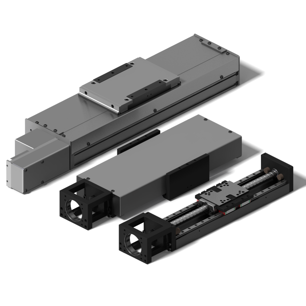
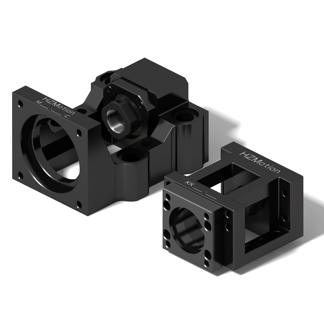
Recommended ratio is product-specific: values such as 5:1, 15:1, 30:1 or higher often refer to different motors, algorithms, stiffness and performance goals. Use the selected servo manual and machine response.
05 / Selection and tuning
Five steps from calculation to repeatable machine validation
- Freeze mechanics and dutyActuator, lead, stroke, mass, orientation, process force and full cycle.
- Reflect inertiaMoving mass, screw, coupling, brake and all rotating elements.
- Screen four quantities togetherMaximum speed, peak torque at speed, RMS torque and vendor-allowed inertia ratio.
- Check interface and energyFlange, shaft, coupling, brake-motor length, drive, regeneration and supply.
- Tune safelyLimit travel and torque, correct looseness/misalignment, then raise response while logging vibration, settling and heat.
Power cannot replace speed, peak, RMS, inertia and regeneration checks.
That is an experience value in some contexts, not a cross-brand mandatory line.
It cannot create missing torque, speed or thermal capacity or repair mechanics.
It can reduce ratio while adding rotor inertia and cost; verify actual response.
Filters suppress particular resonance; misalignment, looseness and weak bases need mechanical correction.
06 / Quick answers
Servo inertia matching questions
Is a 5:1 load-to-motor ratio mandatory?
No. It is a useful first screen in some systems, but allowable ratio depends on the motor, drive, stiffness and response target.
Why does an axis vibrate when the ratio is acceptable?
Coupling, belt, slender screw, motor bracket, base and mounting surfaces can resonate. Inspect mechanics before tuning.
Why does a motor overheat when peak torque passes?
Peak torque is short-term capability. Excess cycle RMS, poor cooling, ambient temperature or regeneration can still overheat the system.
Will a larger motor shorten cycle time?
Only if torque, speed, heat or response is the real limit. It cannot solve screw critical speed, weak structure, guide load or control constraints.