Published:2026-11-10 00:00:00
Updated:
Axial stiffness · Parallel paths · Nut position
Follow the load path through the complete axis
The same thrust can produce a different displacement at another working position. Modeling shaft segments, supports, nut and joints with the correct series and parallel relationships separates position effects from structural improvements.
01 / What is being evaluated
Define the load, measurement point and reference
The same feed axis can show different elastic displacement when the same thrust is applied near the axial locating end and farther away. The screw is elastic, but position also changes the loaded shaft length and the relationship between supports and joints. A nut-stiffness value alone rarely explains the response of the complete axis.
This article evaluates quasi-static, small incremental displacement along the screw axis. The reference is the common rigid structure supporting the end assemblies, and the rotational coordinate is held constant. Torsion, control-loop motion, thermal drift, guide pitch and working-point offset are excluded. Add those effects separately where the application requires them; the resulting curves are not a complete machine-position error prediction.
| Condition to define | Suggested record | Why it changes the interpretation |
|---|---|---|
| Load | Direction, application point, increment and initial load state | Contact stiffness and load paths can change with state |
| Measurement and reference | The fixed reference used for carriage displacement | Different locations include different joints and base deformation |
| Nut position | x from the left axial support reference, together with total spacing L | Defines shaft segment lengths rather than just a machine coordinate |
| Restraint and control | Axial locating ends, rotational holding, feedback and loading rate | Separates mechanical compliance from rotation or controller motion |
Stiffness k = ΔF/Δδ and compliance c = Δδ/ΔF are reciprocals. Using increments makes clear that a slope is being evaluated around a specified preload and contact state. If loading separates a contact, causes slip or enters a strongly nonlinear range, use the appropriate force–displacement relationship instead of extending one constant stiffness indefinitely.
02 / Equivalent paths
Build each series branch before combining the ends
With axial reaction at the left end only, load returns through the nut, left screw segment and left support. A right-end radial support does not automatically provide a second axial path. If both ends are designed to restrain axial displacement, the load at the nut can return through two paths to the same reference structure. They carry load at a common node displacement, so the paths act in parallel.
kL = [1000x/(EA) + 1/kbL]⁻¹
kR = [1000(L−x)/(EA) + 1/kbR]⁻¹
k_bL and k_bR represent the effective axial stiffness of each support bearing assembly and its local housing connection. Combine each shaft segment in series with its own support to obtain k_L and k_R. A is the selected equivalent axial section. For a stepped shaft, add the segment compliances using their individual lengths and areas rather than using the largest visible diameter throughout.
kend = kL + kR
1/kaxis = 1/kend + 1/kn + 1/kc; δ = F/kaxis
| Structural part | Combination | Avoid counting twice |
|---|---|---|
| Left shaft segment and left support | Series compliance within one branch | The local housing connection already included in k_bL |
| Right shaft segment and right support | Series compliance within one branch | A radial-only support cannot be added as an assumed axial path |
| Left and right axial paths | Parallel stiffness at their common node | Do not add the two branch compliances as if they were in series |
| Nut and common mounting connection | Series compliance with the end-path network | Do not separately add parts already included in measured assembly stiffness |
This network assumes stable end references and branches coupled only through the common node. If base bending moves the two supports, or a plate couples their reactions, add the appropriate base compliance or coupled model. Assigning the same physical plate deformation independently to both branches can count it twice and obscure the actual relationship.
03 / Position example
Compare displacement under the same 600 N increment
Use an independent model with axial support spacing L = 1,000 mm, equivalent solid-rod diameter 16 mm and E = 210,000 N/mm², giving A = 201.06 mm². Assign each end support an effective stiffness of 150 N/μm, the nut contact 180 N/μm and the common connection 120 N/μm. These assumed values explain the network; they are not measurements or ratings for an HZMotion model.
Apply an axial increment F = 600 N and assume the contact state remains unchanged throughout loading. Compare axial support at the left end only with axial support at both ends, keeping the other parameters the same. At x = 500 mm, each shaft segment has stiffness about 84.45 N/μm. In series with a 150 N/μm support, each end branch becomes approximately 54.03 N/μm.
| Nut position x | Single-end k_axis | Single-end δ | Dual-end k_axis | Dual-end δ |
|---|---|---|---|---|
| 200 mm | 39.54 N/μm | 15.18 μm | 45.91 N/μm | 13.07 μm |
| 500 mm | 30.87 N/μm | 19.44 μm | 43.21 N/μm | 13.89 μm |
| 800 mm | 25.31 N/μm | 23.70 μm | 45.91 N/μm | 13.07 μm |

In the single-end model, moving the nut away from the axial locating end lengthens the shaft segment transmitting load and increases its compliance. In the symmetric dual-end model, both ends provide a return path. At midspan neither branch is short, so total stiffness is lowest there and the curve is symmetric. Unequal end-support stiffness would change that symmetry.
At midspan, the two parallel branches give k_end ≈ 108.06 N/μm. After adding nut and common-connection compliance, the complete modeled axis has only about 43.21 N/μm. This explains why improving the supports can yield less overall improvement than a shaft-only calculation suggests: the load still crosses other compliant components.
05 / Measurement
Measure the axis, then separate accessible contributions
At representative nut positions, record axial force and displacement with an agreed loading arrangement. Keep the load point, rotational restraint, temperature, measurement direction and reference consistent. The displacement reference should move as little as possible under load; a bending sensor bracket adds its own compliance to the reading.
| Measurement relationship | Contribution being investigated | Boundary to record |
|---|---|---|
| Carriage relative to fixed reference | Total axial response under the chosen loading conditions | Whether base, guide and control-loop effects are included |
| Support housing relative to mounting base | Housing attachment and local base displacement | Do not cross an additional undefined flexible path |
| Shaft end relative to support housing | Support-bearing and shaft-clamping displacement | Use an accessible, reliable reference without rotating interference |
| Opposite sides of the nut-bracket/carriage connection | Relative deformation or slip in the common connection | Instrument only where drawing and access conditions allow |
- Record the initial stateConfirm assembly, preload and temperature, and use the approved static-load range.
- Cover several positionsChoose representative near-end, middle and far-end locations with the same loading arrangement.
- Load and unload in stepsRecord actual force and settled displacement at each step, retaining loading direction.
- Compare incremental slopesCalculate ΔF/Δδ within the same contact regime; do not fit across a clearance or slip discontinuity.
- Return to the structureRelate measured compliance to the actual support, nut and joints before choosing a change and repeating the measurement.
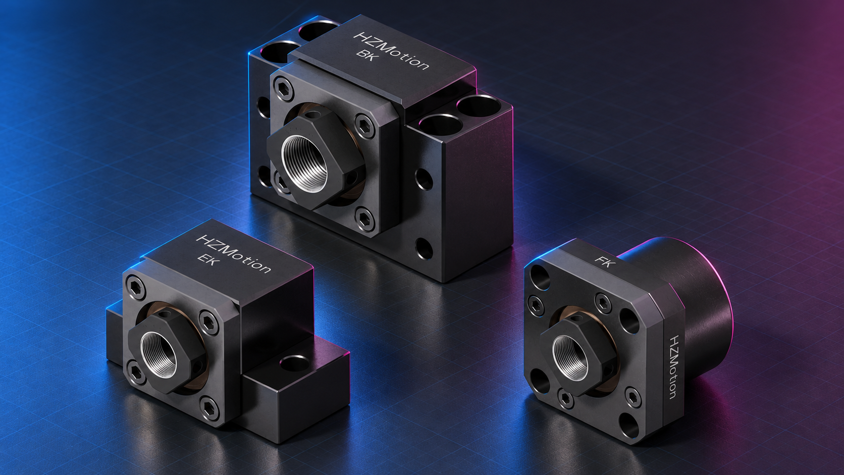
HZMotion actuators and HZM worktables combine screw drive, guides and mounting structure into motion units; support units and nut brackets provide component options. Family names identify structures but do not supply every stiffness needed in this model. Start with the HZM structure description and support-unit catalog, then request model-specific force–displacement or structural information.
Specify allowable displacement at a stated load instead of asking only for “high rigidity.” Include the working-position range, force direction, initial preload, mounting base and measurement reference. Those details let component data be translated into an axis requirement.
06 / Questions
Common axial-stiffness modeling questions
Does fixing both ends make the complete axis four times stiffer?
Not as a general claim. A fourfold ratio can arise for an ideal uniform shaft with rigid axial end supports when particular weakest positions are compared. Support, nut and joint compliance change the improvement of the complete axis.
Why are the two ends not part of one long series chain?
The left and right paths connect the same loaded node to the fixed reference and carry load at the same node displacement, so their stiffnesses add. The shaft segment and support within each path are in series.
Can catalog nut stiffness be used as complete axis stiffness?
No. Establish the stated load, preload and measurement scope, then include the screw, supports and actual connections. If a measured assembly value already includes a component, avoid adding it again.
Can greater preload remove every axial displacement?
No. Preload can change contact state and incremental stiffness while also affecting friction, temperature and internal load. Shaft extension, housing joints and base deformation still require their own evaluation.