Published:2026-10-29 00:00:00
Updated:
Cutting loads · Moments · Compliance
Follow the load path back from the cutting point
When an axis participates in machining, it must both position the workpiece and maintain its position relative to the tool under load. Defined cutting forces, application points and displacement limits provide a sound basis for comparing actuators and worktables.
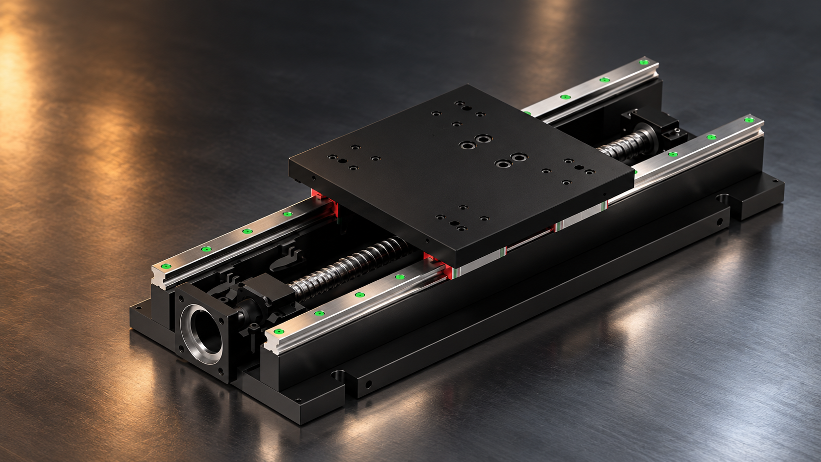
01 / Load cases
Separate workpiece mass from cutting force
Two systems may both move a 20 kg workpiece without being suitable for the same machining task. A handling axis mainly addresses gravity, acceleration and positioning. A machining axis must also maintain the relative position between tool and workpiece during contact. Cutting-force direction and application point change with the toolpath, while deflection, vibration and temperature affect the result.
Start with a load-case sheet. Workpiece and fixture mass determine gravity and inertia. Cutting forces require information about material, tool, engagement, feed and operation, followed by reliable process data or representative cutting trials. A payload rating in kilograms cannot be directly converted into machining capability.
| Source | Data required | Main checks |
|---|---|---|
| Workpiece and fixture | Combined mass, center of gravity and orientation | Gravity, acceleration and eccentric moments |
| Cutting process | Three force components, contact position and process changes | Guide loading, drive force, deflection and vibration |
| Motion cycle | Speed, acceleration, stroke and cycle time | Peak/continuous drive capability, heat and settling |
| Installation | Base support, fasteners, overhang, fixture and spindle connections | The complete structural load path |
| Machining target | Dimensional/geometric tolerances, surface finish and inspection method | Tool-to-workpiece displacement and actual cutting results |
Create simultaneous load cases: the cutting force at one tool position together with gravity, inertia and other forces at that instant. Evaluate several positions and identify the governing cases. Do not combine unrelated directional peaks that never occur together, or discard direction by retaining only a single “total force.”
02 / Application point
The same force produces a different moment at a different height
A force near the carriage center and the same force applied at the top of a tall fixture impose different demands on the guides. Define the coordinate system and reference point first. Use r for the position of the tool contact relative to that reference and F for the simultaneous force vector. The cross product gives the moment with consistent signs.
M = r × F For one perpendicular lever arm: |M| = F · h
r is the position vector from the reference point to the force application point. h is the perpendicular distance from the reference point to the force line. Project M onto a specified axis to obtain its component about that axis. Use metres with newtons to obtain N·m.Independent example: a lateral cutting force of 300 N acts 150 mm above the selected guide reference. This force alone produces 300 × 0.150 = 45 N·m. Lowering the fixture so that the height is 75 mm reduces the moment to 22.5 N·m at the same force. The improvement comes from the lever arm, without changing the motor or guide material.
| Assumed cutting force | Perpendicular lever arm | Moment magnitude |
|---|---|---|
| 300 N | 50 mm | 15 N·m |
| 300 N | 100 mm | 30 N·m |
| 300 N | 150 mm | 45 N·m |
| 300 N | 200 mm | 60 N·m |

Next, resolve the loads using the selected model’s guide spacing, block arrangement and catalog coordinates. Check combined loading and life. Allowable moments, dynamic ratings and static ratings serve different purposes and cannot be substituted for each other. See offset-load and moment analysis for reference-point and coordinate considerations.
03 / Comparison
Compare structures under the same operating and mounting conditions
Linear actuators are convenient building blocks for single- and multi-axis equipment. CNC worktables offer a platform for workpieces and tooling. These are integration differences, not a universal ranking of machining capability. Compare specific TKA, TKK or HKK candidates with HZM200–400 worktables using their actual sizes, strokes, configurations and supports.
| Comparison | Linear actuator candidate | CNC worktable candidate |
|---|---|---|
| Load position | Check fixture offsets; stacked axes also load the lower axes | Check workpiece offset and cutting height, not only centered table loading |
| Guidance | Verify rail count, spacing, block separation and preload for the model | Verify the actual guide arrangement and support area; appearance is not load data |
| Base and joints | Confirm continuous or discrete support, fasteners and mounting-surface quality | Confirm foundation, support, fastening and actual base option |
| Fixture interface | Check holes, locating faces and local adapter-plate deflection | Check actual T-slot or other tabletop options, clamping and contact |
| Environment | Confirm protection, lubrication and chip removal; add machine guarding where needed | The same checks apply; a worktable name does not establish coolant protection |
| Acceptance | Measure relative displacement and machining results at agreed loads and tool positions | Use the same criteria and record tuning, temperature and installation |
The HZMotion HZM catalog describes parallel linear guides on a precision base with a ball-screw drive, and lists aluminum, steel and marble base options. It is therefore inaccurate to assume every worktable has a steel base. Elastic modulus is one part of stiffness; section geometry, span, guide arrangement, contact and fastening also matter.
Catalog applications include drilling and small CNC equipment. These examples support a discussion of suitable configurations, but do not establish heavy-cutting capability for every model. Suitability still depends on the combined loads, displacement limits, thermal state and process validation.
Product basis: HZM structure, PDF page 295; base options, page 297; applications, page 298; model data, page 299 onward. Confirm the ordered configuration against its approved drawing.
04 / Compliance
Allocate deflection across the structural path
Machining dimensions depend on the relative position of tool and workpiece. Even a stiff motion axis can be limited by the base, adapter plate, fixture, spindle or tool. Looking at the complete structure helps identify where an increase in stiffness is most useful.
δ = F · Σ(1/ki) 1/keq = Σ(1/ki)
Simplified one-dimensional series model: the segments carry the same directional force and remain linearly elastic. With k_i in N/μm, F/k_i is in μm. Real three-dimensional structures may require rotation, coupling and parallel load paths.Consider an independent example with a 300 N cutting force and four equivalent stiffnesses, all referred to the cutting point in the same direction. These are illustrative inputs, not measurements of an HZMotion product or test machine. Local catalog stiffnesses cannot be inserted without the required geometric and directional conversion.
| Equivalent segment | Assumed stiffness k | Deflection F/k at 300 N |
|---|---|---|
| Base and joints | 100 N/μm | 3 μm |
| Motion axis | 60 N/μm | 5 μm |
| Fixture and clamping | 150 N/μm | 2 μm |
| Spindle and tool | 30 N/μm | 10 μm |
| Total / equivalent | 15 N/μm | 20 μm |
Doubling only the motion-axis stiffness from 60 to 120 N/μm halves that segment’s deflection, but reduces total deflection from 20 to 17.5 μm: a 12.5% reduction. Alternatively, doubling only the spindle/tool segment from 30 to 60 N/μm reduces the total to 15 μm, a 25% reduction. In this assumed model, improving the most compliant segment is more targeted than enlarging the motion axis by default.

First identify the actual structural loop. Where loads split, supports act in parallel or rotations are significant, use an appropriate model, finite-element analysis or measurements instead of continuing to add four scalar deflections. Cutting dynamics also involve mass, damping, natural frequencies and process excitation. Higher static stiffness alone does not guarantee freedom from chatter.
05 / Validation
Progress from controlled checks to representative cutting trials
A selection report should state both the required result and the conditions used to verify it. Unloaded repeatability, displacement under a static force and machining accuracy are different metrics. Returning an axis to the same position does not establish the same tool-to-workpiece error under cutting load.
- Create comparable candidatesFix the workpiece, fixture, tool overhang, stroke, motion and installation conditions. State which parameters may change between concepts.
- Check loads and structureCalculate force and moment at governing tool positions. Check the actual model, drive and thermal conditions, then estimate or measure cutting-point compliance.
- Inspect static and motion behaviorRecord displacement under safe controlled loading and check full-stroke geometry and positioning. Distinguish contributions from axis, fixture and frame.
- Run representative cutsCover the main force directions and overhang conditions. Record tool condition, material, depth, feed, spindle speed and coolant method.
- Inspect under agreed conditionsCheck dimensions, geometry, finish and cycle time with stable installation and temperature. Retain data and unusual-condition records.
| Use case | Conditions to clarify first | Insufficient evidence by itself |
|---|---|---|
| Handling and workpiece positioning | Mass, center of gravity, inertia, positioning and settling | Handling capacity does not establish cutting stiffness |
| Drilling or light machining | Axial/lateral force, contact point and clamping | A single axial-thrust rating |
| Milling with significant lateral force | Combined moments, overhang, compliance and vibration | Motor power or base material alone |
| Fine finish or tight dimensions | Static deflection, thermal drift, dynamic stability and inspection | Unloaded repeatability alone |
A useful review package can be concise: combined workpiece/fixture mass and center of gravity; cutting-force estimates or process data; tool position relative to the table; allowable relative displacement; support drawings; and the proposed inspection method. See accuracy parameters and inspection methods and protective cover selection for related checks.
06 / Questions
Machining-axis selection FAQ
Can stiffness be ignored when the workpiece is light?
No. A light workpiece may still involve a tall fixture, long tool overhang or substantial lateral force. Evaluate the actual forces and their application points.
Is a steel-base system always more suitable than an aluminum-base system?
Material alone is insufficient. Section geometry, span, guide layout, joints and supports change overall stiffness. Compare cutting-point response under the same conditions.
Is sufficient motor thrust enough for cutting?
Thrust is only one requirement. Check guidance, combined moments, deflection, temperature and dynamic stability. Drive capacity cannot replace a structural assessment.
Does repeatability represent machining accuracy?
Not directly. Cutting deflection, tool, spindle, fixture, temperature and process all contribute. Inspect the machined result under defined conditions.
Do drilling and small-CNC applications in the catalog imply heavy-cutting capability for every model?
No. Application examples indicate possible integration uses. Each model, stroke, load, installation and process still requires assessment and validation.