Published:2026-10-29 00:00:00
Updated:
Motor brackets · Replacement and retrofit
Make every changed interface visible before the refit
A new motor has to rejoin the machine’s locating, fastening and drive interfaces. A before-and-after dimension sheet and a clear axial stack expose many problems before they reach the assembly bench.
01 / Establish the baseline
Equal power and flange size do not settle every interface
When a machine is waiting for a replacement motor, a straightforward refit is the ideal outcome. Equal rated power and a familiar flange outline are useful starting points, but they are not the complete check. A few additional millimeters of shaft extension, a different pilot height or a changed mounting thread can alter the relationship between motor, bracket and coupling. A before-and-after worksheet makes those changes visible before assembly.
Start from the known old configuration: complete motor code, brake option, shaft form, bracket model, coupling model and the latest reliable installation record. Then obtain the drawing for the exact new motor variant. Do not mix drawings for different power ratings, brake options or shaft configurations within the same series.
| Interface | Compare old and new | Effect on the installation |
|---|---|---|
| Mounting flange | Outline, reference face and local projections | Face contact and clearance to the bracket |
| Locating pilot | Diameter, tolerance, projection and root geometry | Pilot engagement and possible bottoming |
| Mounting holes | PCD or spacing, number, orientation, hole/thread type and usable depth | Correct fastening without bottoming or inadequate engagement |
| Motor shaft | Diameter, extension, keyway, chamfer and usable cylindrical length | Coupling bore and valid clamping location |
| Rear envelope | Body length, brake, connectors and cable exit | Clearance to frame, guard and cable bend |
| Drive and control | Drive compatibility, encoder, current, brake and parameters | A separate electrical/control review, not proven by mechanical fit |
Mechanical compatibility is only part of replacement acceptance. Torque–speed capability, inertia, thermal duty, braking and control settings must also be reviewed for the actual new motor.
02 / Location and fastening
Verify face contact before tightening the interface
Understand the intended functions of the pilot, mounting face and bolts. Where a pilot provides location, aligned bolt holes do not prove correct shaft location. Conversely, a matching pilot diameter does not guarantee face contact if the pilot projection exceeds the available depth. Additional bolt torque should not be used to close a gap caused by incompatible geometry.
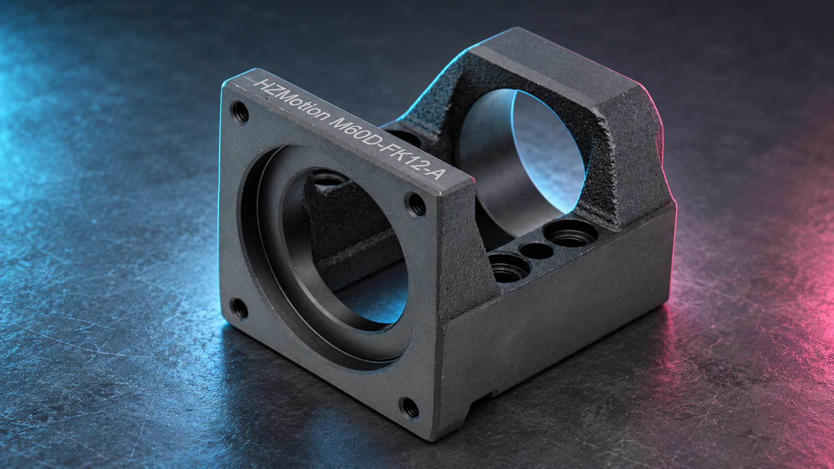
Section 6.1 of the HZMotion motor-bracket manual lists M60D-BK12-C and M60DP-BK12-C. Both have a 50 mm D1 pilot bore and a 70 mm W1 mounting pitch circle in that table. Their motor mounting-hole designation Y is different: M5 for the former and M4 for the latter. Similar overall geometry can therefore conceal an important interface difference in the complete model suffix.
| Manual example | Pilot bore D1 / mm | Mounting PCD W1 / mm | Motor mounting hole Y |
|---|---|---|---|
| M60D-BK12-C | 50 | 70 | M5 |
| M60DP-BK12-C | 50 | 70 | M4 |
Source: HZMotion Chinese motor-bracket manual, section 6.1, PDF page 8. M5/M4 refers to drawing field Y. These values apply only to the stated models and do not establish compatibility with every motor described as a 60-size flange. View the complete drawing.
Clean the locating surfaces, then confirm pilot, hole and face relationships against the drawing. Bolt length must provide the required engagement while retaining any necessary bottom clearance. Through-hole arrangements also need clearance for nuts, washers and tools. If the hole specification changes, establish a fastening arrangement approved for the design rather than accepting any bolt that can be screwed into place.
03 / Axial stack example
What a 2.5 mm increase in shaft extension changes
Let S be the axial distance from the installed motor mounting face to the facing end of the screw-side shaft. Let l be the motor shaft extension measured from that same mounting face toward the coupling. With coaxial, facing shaft ends, the gap is g = S − l. This simplified model addresses shaft-end spacing only; hub engagement and the coupling’s own installation requirements remain separate checks.
g = S − l
gmin = Smin − lmax; gmax = Smax − lmin
| Assumed dimension | Before replacement | After replacement |
|---|---|---|
| Mounting face to screw-side shaft end S | 34.0 ± 0.1 mm | 34.0 ± 0.1 mm |
| Motor shaft extension l | 30.0 ± 0.1 mm | 32.5 ± 0.1 mm |
| Nominal shaft-end gap g | 4.0 mm | 1.5 mm |
| Extreme gap range | 3.8–4.2 mm | 1.3–1.7 mm |

In this example, increasing the shaft extension by 2.5 mm reduces the gap by 2.5 mm. It does not establish whether a 1.3–1.7 mm gap is acceptable. Compare the result with the actual coupling’s installation dimensions, insertion requirements and permitted deviations. Even with a positive end gap, a hub can contact a shoulder or clamp partly over a chamfer.
Moving the coupling toward one shaft is not automatically a complete remedy. Recheck usable engagement on both sides, screw access, key position and the axial displacement conditions in service. A change to bracket length or the addition of a designed adapter requires renewed checks of location, fastening and stiffness. Arbitrary stacks of washers are not a substitute for that interface design.
04 / Drive connection
Three lengths require three separate checks
The shaft-end gap describes the relationship between the two shafts. Hub engagement describes the relationship between each shaft and its coupling hub. The coupling’s specified installation length relates to its flexible or transmitting elements. Treating all three as one insertion depth can conceal an otherwise avoidable assembly error.
| Length to verify | Acceptance basis | Frequently missed feature |
|---|---|---|
| Motor-side usable engagement | Coupling-hub requirement and the new motor’s usable shaft cylinder | Root fillet, end chamfer and keyway termination |
| Screw-side usable engagement | Screw end drawing and the opposite hub requirement | An old witness mark is not proof of a valid clamping position |
| Shaft-end spacing | Installed dimensions and coupling design requirements | Shaft ends may contact inside the hubs out of sight |
| Specified coupling installation length | Instructions for the actual coupling model | A flexible element is stretched or compressed away from its specified condition |
| Fastening and service clearance | Required tool operation and later removal | A screw hidden by the bracket cannot be tightened as intended |
Inspect the coupling itself during the replacement. Damaged hub clamping surfaces, thread problems and aged flexible elements do not disappear when a new motor is installed. If the new shaft diameter differs, review both bores and the complete coupling model’s torque, speed and misalignment capability. An improvised rebore should not be treated as retaining the original catalog rating.
If the flange seats correctly but starting torque or rotational resistance rises after coupling connection, identify the assembly stage at which the change appears. Check alignment, hidden shaft-end contact and coupling axial condition. For braked axes or suspended loads, follow the machine’s maintenance procedure with the appropriate personnel and restraints; forcibly turning the shaft is not a universal diagnostic method.
05 / Replacement acceptance
Record changes before controlled return to service
A replacement record turns “a motor was changed” into a configuration that the next maintenance team can understand. Alongside model codes, retain measured spacing, coupling positions and confirmation of relevant settings. Resume operation from a verified mechanical and electrical state, then validate the machine in the stages required by its procedure.
- Record both configurationsKeep old/new complete motor codes, drawing revisions, bracket and coupling models, and a list of changed interfaces or parts.
- Confirm the static installationVerify face seating, location, usable hub engagement, shaft-end spacing and specified fastening. Remove tools and temporary supports.
- Confirm electrical and control adaptationCheck motor identification, encoder, brake, limits and relevant parameters under the drive and machine instructions. Verify direction and travel boundaries.
- Validate operation in stagesUnder controlled conditions, check low-speed movement, then the required travel, speed and working load. Observe vibration, temperature and drive behavior.
- Establish a new acceptance baselineRecord positioning and repeatability results, noise/vibration observations, steady operating conditions and the acceptance decision.
| Acceptance record | Evidence to retain | Conclusion that does not automatically follow |
|---|---|---|
| Interface agreement | Compared drawings, measured dimensions and final assembly photographs | Equal flange outline does not establish every interface |
| Drive connection | Both engagement positions, end gap and coupling condition | No shaft-end contact does not establish correct coupling installation |
| Operating behavior | Speed, load, drive state and temperature under comparable conditions | Smooth no-load running does not prove rated-duty suitability |
| Axis accuracy | Positioning and repeatability measured by the machine acceptance method | Higher encoder resolution does not automatically reduce complete-axis error |
Changed motor inertia or torque characteristics can alter control response even after the mechanical interface has passed inspection. Keep interface checks, sizing review and control commissioning as separate records. This avoids using tuning to conceal interference or attributing every vibration to the bracket. Related checks include servo inertia matching and linear-axis accuracy inspection.
06 / Frequently asked questions
Common replacement decisions
Can motors with equal rated power and flange size be directly exchanged?
Not from those two facts alone. Compare pilot, holes and threads, shaft diameter and extension, brake and connector space. Independently verify the drive, encoder, torque–speed capability and control settings.
Does a positive shaft-end gap prove correct coupling installation?
No. The coupling must also meet its specified installation length, engagement, fastening and allowable deviation requirements. A positive gap only rules out contact under the static dimensional conditions checked.
Can the bolts pull a small flange gap closed?
First establish whether the cause is pilot bottoming, a burr, interference or an incorrect interface. Normal fastening should not be used to overcome incompatible geometry. Restore the specified seating conditions before tightening.
Why verify working load when low-speed running is smooth?
The new motor may have different inertia, torque characteristics, thermal conditions or control compatibility. Low-speed no-load running covers only part of the duty; acceptance must cover the machine’s required operating conditions.
Can the existing coupling be reused?
That depends on both shaft interfaces, component condition, torque and speed capability, and installation space. Check hubs, fasteners and flexible elements, then reinstall according to the actual model instructions.