Published:2026-09-14 09:30:00
Servo motor bracket interface checks
Check every interface from motor to screw
A motor bracket must match the flange, locating pilot, PCD, shaft extension, centre height and coupling space together. Establish the dimensional relationships before choosing a complete HZMotion standard or integrated part number.
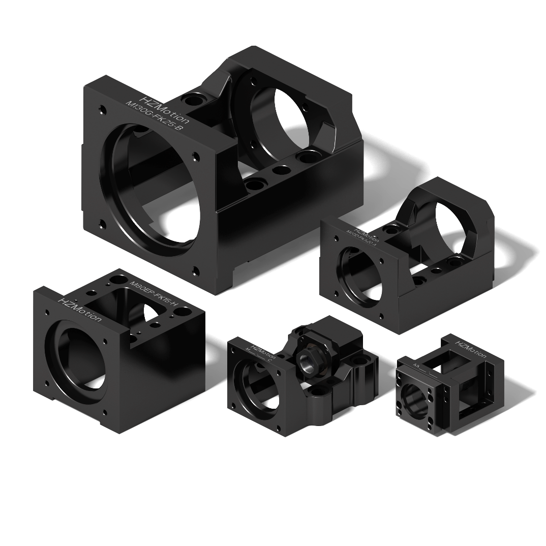
01 / Prepare the drawings
Place the motor, bracket and screw end in one assembly relationship
A motor bracket locates the motor relative to the screw support. Start with the complete motor designation and dimensional drawing, the screw-end drawing, and the bracket and support-unit drawings. Add the coupling bore sizes, hub lengths, outside diameter and installation requirements. Motor power contributes to drive sizing; it does not define the mechanical interface.
Flange outline, pilot diameter and projection, bolt pattern, shaft diameter and extension, plus brake and connector clearance.
Bearing journal, shoulder, locknut thread and coupling seat. Standard brackets also require the separate support-unit interface.
Coupling diameter and length, shaft engagement, end gap and access for the clamping tool.
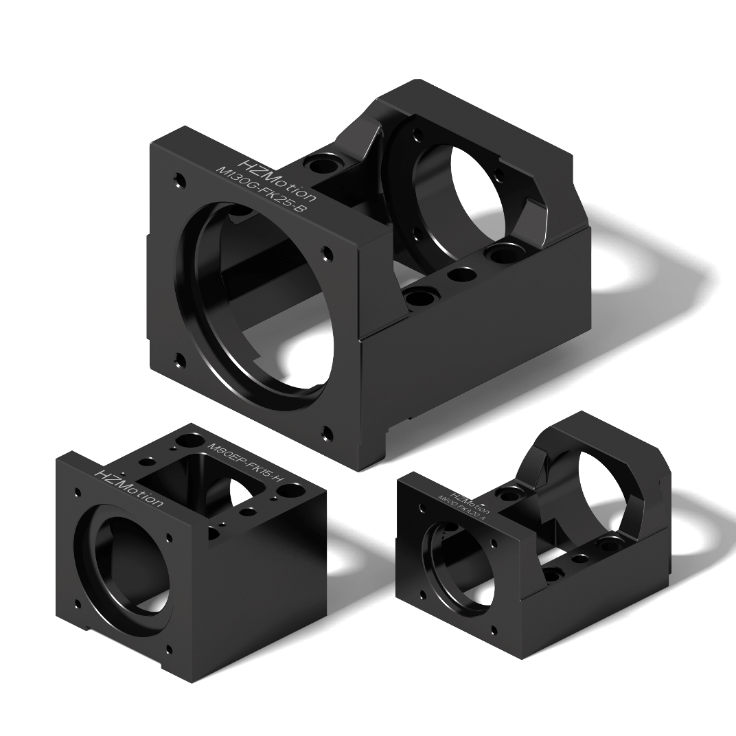
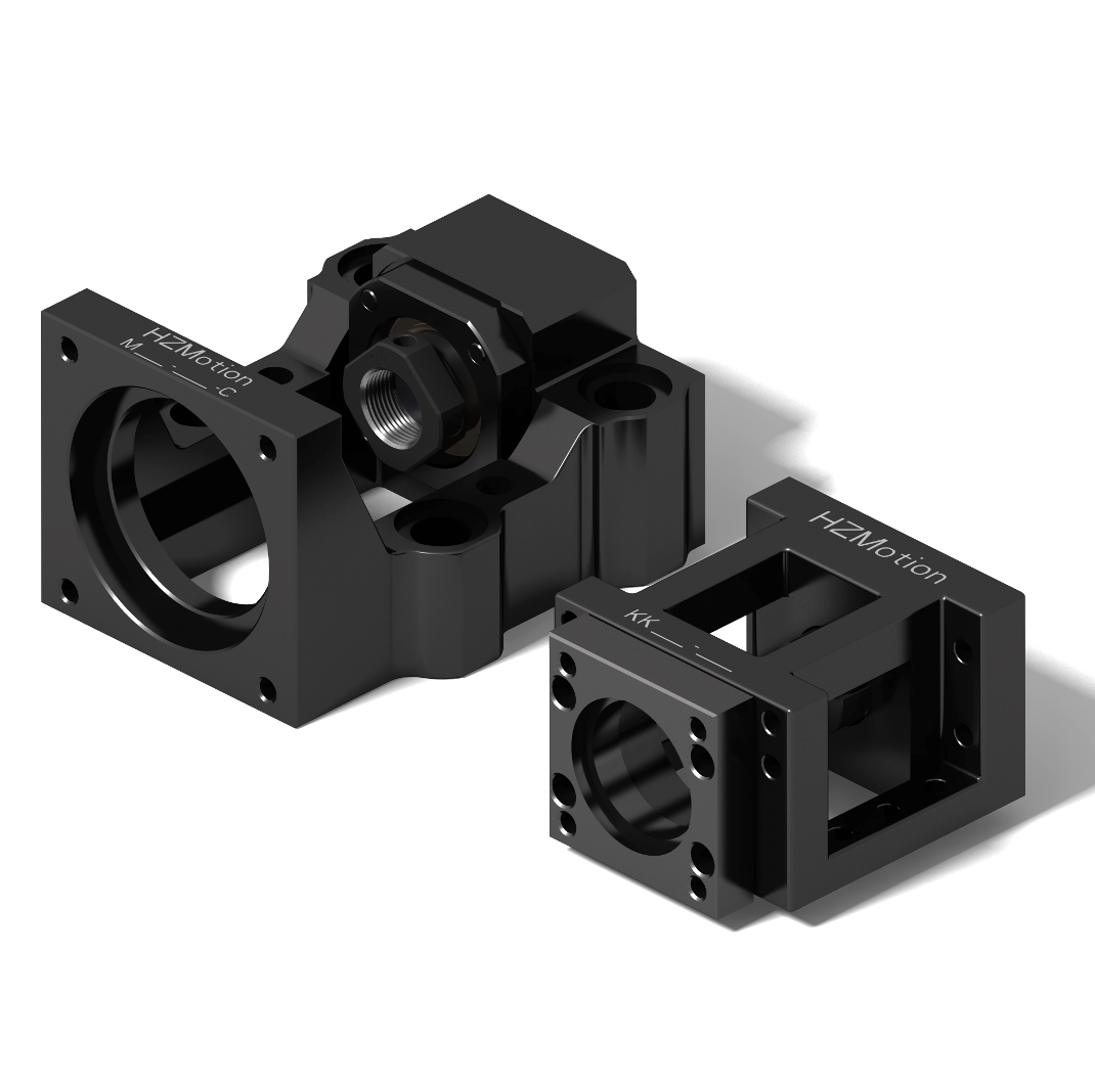
02 / Motor dimensions
Check the flange, pilot and bolt circle separately
| Feature | Compare | Common omission |
|---|---|---|
| Flange outline | Motor mounting face, bracket envelope and available installation space. | Equal flange width does not guarantee equal pilot, bolt pattern or shaft extension. |
| Locating pilot | Male pilot diameter and projection against locating-bore diameter, usable depth and tolerances. | The pilot must not bottom before the mounting faces meet. Check chamfers and root-radius interference. |
| Hole pattern / PCD | Bolt count, pitch-circle diameter and angular positions, or rectangular coordinates. | PCD is the diameter of the circle through hole centres; adjacent-hole spacing in a square pattern is different. |
| Threads and fasteners | Thread size, effective engagement, through or tapped holes and screw-head clearance. | Identical hole centres can use different threads. Bolts must not bottom or interfere with rotating parts. |
| Shaft and accessories | Shaft diameter tolerance, extension, keyed or plain shaft, brake and connector orientation. | A front view alone misses axial length, cable routing and service access. |

For four equally spaced holes forming a square on one circle, adjacent centre spacing a gives PCD = √2 × a. Do not apply this relation to a different hole layout.
03 / HZMotion example
Two 60-series interfaces can use different mounting threads
PDF page 8 of the HZMotion Chinese motor-bracket manual lists the following BK12 integrated configurations. Their locating bore, bolt circle and main dimensions match, while the motor-side mounting threads differ. Preserve the complete 60D or 60DP interface code.
| Part number | Locating bore D1 (mm) | PCD W1 (mm) | Mounting thread Y | Centre height h (mm) | Housing length L (mm) |
|---|---|---|---|---|---|
| M60D-BK12-C | 50 | 70 | M5 | 25 ±0.02 | 83 |
| M60DP-BK12-C | 50 | 70 | M4 | 25 ±0.02 | 83 |

This example illustrates an interface difference; it is not a universal ordering rule for a “60 flange.” The bearing journal d1 is 12 mm in both configurations. It is neither the motor-shaft diameter nor the nominal screw diameter. Motor extension, coupling length and shaft-engagement requirements still need separate verification.
04 / Screw side and height
Align the axes and ensure every locating face seats correctly
| Location | Check | Why it matters |
|---|---|---|
| Support interface in a standard bracket | Full fixed-end designation, locating diameter or bore, mounting face, screws and support height. | A/B/H/L interfaces differ; appearance or nominal screw diameter is not a sufficient interchange rule. |
| Shaft end in an integrated bracket | Bearing-journal diameter and tolerance, shoulder, fillet, locknut thread, collars and seal positions. | C/KK already contain bearings, but the shaft end must still follow the corresponding installation drawing. |
| Centre height and datums | Motor, fixed-end and opposite support axes relative to the machine datums. | Compare installed heights, including baseplates or controlled shims, rather than isolated catalogue height values. |
| Axis loading | Bearing arrangement, preload, axial load, speed and duty cycle. | Physical fit is only the first check. An integrated configuration must also satisfy fixed-end operating requirements. |
After identifying the BK12 bearing journal, the screw section entering the coupling can still have a different diameter. Mark the bearing seat and coupling seat separately on the complete shaft-end drawing supplied to machining and purchasing.
05 / Coupling envelope
Diameter, shaft engagement and end gap must all be acceptable
- Check both boresMatch one bore to the motor shaft and the other to the screw coupling seat, including tolerances and keyed or clamping arrangements. The two bores need not be equal.
- Check usable shaft engagementExclude chamfers, shoulder fillets and non-clamping regions. Both hubs must meet the coupling requirement for shaft insertion and engagement.
- Check end gap and installed lengthUse the coupling drawing to set the gap. Avoid shaft ends contacting each other or an assembly that forces axial extension or compression of the coupling.
- Check rotating and tool envelopesInclude the maximum rotating diameter, projecting screws, bracket cavity and guard. Confirm access to the hub-clamping screws.
- Check operating capabilityVerify peak and continuous torque, speed, inertia and permissible misalignment, including the manufacturer’s conditions for combined radial, angular and axial offsets.
- D
- Axial distance between the selected motor mounting datum and the opposing shaft-location datum
- Lm / Ls
- Motor and screw-shaft projections from those datums into the same installation space
- g
- Remaining shaft-end gap; a positive value only confirms that the ends do not geometrically overlap
As a geometry example only, D = 70 mm, Lm = 32 mm and Ls = 36 mm give g = 2 mm. This is not a recommended gap. The chosen coupling must also satisfy its specified end distance, hub positions and overall installed length. Include any adapter-flange thickness and changed datums in the dimension chain.
06 / HZMotion families
Filter by installation relationship, then select the complete part number
| Family | Structure and matching route | Continue by checking |
|---|---|---|
| A | Standard bracket combined with the corresponding FK/FKA fixed end. | Motor interface code, specific support unit and coupling space. |
| B | Standard bracket; individual models cover FK, MBK or WBK combinations. | The exact model row; a heavy-duty arrangement can change axial packaging. |
| H | Standard bracket with the corresponding FK configuration. | External mounting dimensions, auxiliary features and assembly space. |
| L | Standard bracket with a corresponding FKA unit and lower-centre-height options. | Machine datum and opposite support height; do not substitute by appearance for Type A. |
| C | Integrated bracket with model-specific BK/EK/AK/SBK-related bearing configurations. | Shaft-end machining, bearing configuration, full motor interface and end-support pairing. |
| KK | Integrated bracket with the applicable motor adapter flange. | Adapter version, locating features and the resulting axial space. |
This family table narrows the search; the specific drawing remains decisive. Built-in bearings reduce separate interfaces but do not remove the need to check the base, shaft end and installed alignment.
07 / Selection worksheet
Turn a fit check into a reviewable set of inputs
| Information group | Provide |
|---|---|
| Motor | Brand, series, full designation, power, rated and peak torque, maximum speed, brake option and dimensional-drawing revision. |
| Mounting face | Flange outline, pilot diameter and projection, PCD or hole coordinates, hole count, threads and usable depth. |
| Both shafts | Motor and screw coupling-seat diameters and tolerances, usable projections, keyways, shoulders and shaft-end gap. |
| Support and base | Full fixed-end designation or integrated configuration, bearing-seat drawing, centre height, datums, travel and opposite support. |
| Coupling | Full designation, bore sizes, engagement, outside diameter, installed length, torque, speed and misalignment requirements. |
| Duty and space | Load, acceleration, cycle, environment, cable routing, guards, tooling and removal access. |
During installation, clean the locating surfaces and ensure the faces seat correctly. Do not pull an interfering pilot into its bore with the bolts or hammer the motor shaft to fit the coupling. Yaskawa’s rotary-servomotor manual calls for shaft alignment and avoidance of installation shock that can damage bearings or encoders. Use the selected motor and coupling documents for actual alignment limits, tightening torques and permissible shaft loads.
After final tightening, check full travel, current, vibration and temperature trends. A coupling’s misalignment capacity is not a reason to omit bracket and screw alignment.
08 / FAQ
Frequently asked questions
Can equal-power servo motors share the same bracket?
Not on power alone. Brands or series can differ in pilot, hole pattern, shaft diameter and extension. Brake and connector options can change the space required even within a motor family.
Can I draw a tight pilot into the bracket using the bolts?
Check diameter tolerances, burrs, fillets and effective depth first. The locating faces must seat properly; bolt force should not conceal interface interference.
Does an integrated bracket also need a separate BK support unit?
Check the configuration and supplied parts. Type C assemblies already contain bearings; BK in the designation identifies the corresponding configuration, not a requirement to add another complete BK housing.
Does 12 in M60D-BK12-C identify the motor shaft?
No. In the illustrated drawing, d1 = 12 mm identifies the screw bearing journal. Check the motor shaft and screw coupling seat separately against their drawings.
Is a coupling acceptable if its diameter is smaller than the cavity?
Also check shaft engagement, end gap, installed length, projecting fasteners, tool access, torque, speed and misalignment conditions.