Published:2026-10-29 00:00:00
Updated:
Precision assembly · Mounting interfaces
Preserve the stage condition as it becomes part of the machine
A stage runs smoothly during inspection, yet its resistance changes after mounting bolts are finally tightened. The difference deserves investigation. Once connected, the stage and machine base form a constrained structure. Reliable mounting requires both correct location and contact conditions that agree with the design.
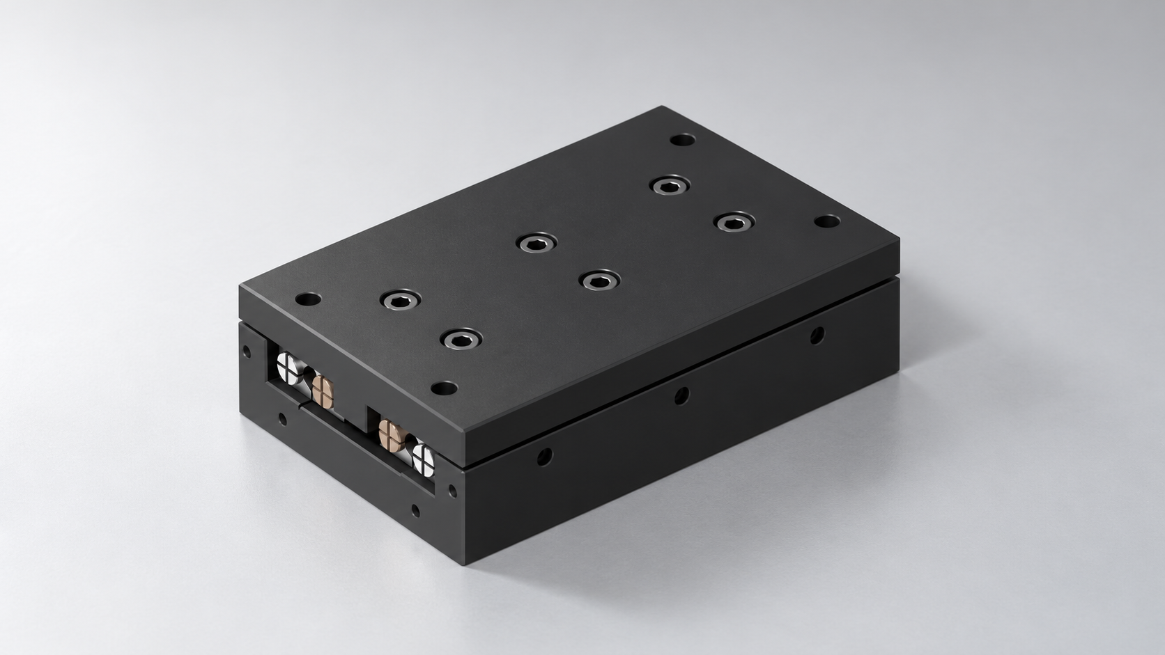
01 / Mounting datums
Contact conditions come before the final measurement
The stage mounting face, machine base and fasteners form a load path. A burr, trapped chip or unsuitable support can cause bolts to pull the assembly into uneven contact. The upper table may then behave differently even though every fastener is tight. Treat secure fastening and correct contact as separate checks.
| Interface | What to establish | Often overlooked |
|---|---|---|
| Primary mounting face | Specified face, contact region and supporting structure | Edge burrs, coating buildup and particles trapped in oil |
| Lateral location | Specified side datum, locating pins or approved alignment method | Unplanned side clamping introduces another constraint |
| Holes and entries | Position, diameter, counterbore or countersink and tool access | Raised edges or partial head/washer support |
| Base stiffness and support | Local thickness, span and load support | A bolt pulling an unsupported thin section into deflection |
| Upper fixture | Contact face, screw length, center of gravity and load path | Fixture deformation transmitted into the upper table |
Use the applicable CRU or HZM worktable drawing for actual mounting requirements. Confirm base flatness, location methods and support regions for the specific model. Resolve missing requirements before machining and assembly.
Do not alter internal guide adjustment or preload to compensate for a machine-base error. Where shimming or alignment correction is required, use an approved method and controlled contact region. Loose local shims are not automatically adequate support.
02 / Dimensional stack
Calculate penetration, then assess real engagement
Blind-hole depth can mean drilled depth, tapped depth or the depth of complete usable threads. The bolt tip has a lead or chamfer, while the hole may include incomplete threads and a drill point. Treating all of these dimensions as available engagement can cause bottoming or leave fewer complete threads engaged than intended.
lin = Lb − tstack
lin: bolt penetration measured from the threaded-hole entrance plane. Lb: bolt length under the convention for that head type. tstack: actual clamped stack from the same length reference to the hole entrance. Check the reference separately for countersunk heads.
| Dimension | Meaning | Misinterpretation to avoid |
|---|---|---|
| Clamped stack tstack | Distance from the bolt-length reference to the target-hole entrance | Ignoring washers, counterbores or steps |
| Penetration lin | Geometric length entering the target hole | Counting all inserted length as full-thread engagement |
| Effective engagement le | Actual overlap of complete internal and external threads participating in the designed connection | Including entry chamfers and incomplete end threads |
| Usable internal depth | Available space after accounting for bottom geometry, full-thread range and prohibited contact | Using the deepest drill point as a permitted bolt-tip position |
| Bottom clearance | Actual space between the bolt end and limiting surface | Assuming a tightening torque proves that the bolt has not bottomed |
For example, a 20 mm bolt and an 8 mm clamped stack give 12 mm nominal penetration when measured from compatible references. A drawing that states only “drilled depth 16 mm” is still insufficient to approve that bolt. Full-thread depth, tip geometry, required effective engagement, length tolerances and clearance to moving parts remain to be checked.
For tolerance checks, maximum penetration uses maximum bolt length minus minimum stack thickness; minimum penetration uses the opposite combination. Assess effective engagement from the overlap of complete threads. Its requirement depends on material, thread geometry, load and connection design, so a fixed multiplier is not a universal stage rule.
03 / Assembly process
Make tightening a sequence that can be observed
- Record the initial conditionUse controlled support, loading and measurement conditions to record travel, resistance trends and geometric checks. Do not create an overturning risk with an unsecured stage.
- Inspect contact and holesCheck datums, hole entries and fasteners. Confirm bolt specification, length, head contact and tool clearance against the drawing.
- Seat and align the assemblyUse the specified datum and location method. Do not pull misaligned holes or unsupported faces into position by forcefully tightening bolts.
- Tighten in the specified stagesUse the assembly-specific sequence and stage values, keeping thread surface conditions consistent. If torque requirements are absent, obtain technical confirmation instead of selecting a value by guesswork.
- Recheck key stagesObserve whether a change in motion coincides with a tightening stage. Stop progression and inspect contact and dimensional stacks when a new symptom appears.
- Verify the final operating assemblyComplete agreed checks with the final fixture, load and temperature conditions. Retain tightening parameters and measurement results.
Equal torque does not necessarily produce equal clamp force. Thread and under-head friction, lubrication, coatings, washers and reuse affect the relationship. Record torque with the fastener specification and surface condition. A value from a different component should not be transferred without justification.
| Stage | Controlled conditions | Main observation |
|---|---|---|
| Initial baseline | Support, temperature, direction, speed and load | Original range and motion trend |
| Seating and initial tightening | Specified datums, contact and location method | Contact consistency and unintended side loading |
| Staged tightening | Specified sequence and stages; same measurement method | Which step and region first show a change |
| Final tightening and fixture installation | Final connection and operating load | Motion, geometry and process positions against acceptance criteria |
04 / Comparison
Measure resistance and accuracy as separate outcomes
Movement resistance, travel geometry and positioning performance describe different observations. A resistance increase at one position cannot directly be converted into a positioning error. Conversely, reaching a commanded position does not establish suitable guide contact or mounting conditions. The measurement plan must match the performance relevant to the machine.
| Observation | Comparison method | Interpretation limit |
|---|---|---|
| Movement resistance or drive load | Same speed, direction, load, temperature and position | Motor current also depends on control and transmission behavior; it is not a direct guide-friction reading |
| Travel geometry | Straightness, parallelism or angular change against the defined datum and positions | Gauge mounting, probe location and base deformation influence readings |
| Positioning performance | Agreed load, speed, direction, cycles and temperature | Report repeatability separately from travel-wide positioning error |
| Local interference | Inspect screw ends, fixtures, cables and guards | Position-dependent contact can differ from general mounting deformation |
A change that appears immediately after an external tightening step gives a useful investigation lead, but timing alone does not prove product damage. Check the base, contact and fastener geometry under controlled conditions. Any release of external mounting bolts, support arrangement and repeat measurement must follow the assembly procedure; do not loosen screws experimentally during loaded operation.
If external causes have been excluded and localized sticking, abnormal noise, raceway marks or debris remain, preserve the condition and arrange inspection. Document the external causes already ruled out and the symptoms that remain to support the service assessment.
05 / Assembly record
Keep the conditions that made the result possible
| Category | Minimum content | Purpose |
|---|---|---|
| Product and base | Full model, drawing revision, base drawing and mounting-face inspection | Trace the actual interface |
| Fasteners | Specification, grade or material, length, quantity, washers and surface condition | Confirm connection and dimensional-stack inputs |
| Holes and engagement | Entrance reference, full-thread depth, penetration range and engagement requirement | Check bottoming, protrusion and inadequate overlap |
| Process | Location method, tightening sequence and stages, tool and date | Retain a repeatable assembly method |
| Verification | Before/after data, load, speed, temperature and acceptance criteria | State the conditions under which results are comparable |
A useful record lets the next engineer reproduce the check. It does not have to be complicated, but statements such as “installed” or “feels normal” need a position, method and set of conditions behind them.
06 / Frequently asked questions
Five mounting-interface questions
Is one base-flatness requirement suitable for all precision stages?
No. The requirement depends on size, construction, accuracy objectives and support. Use the model drawing and approved machine requirements; resolve missing conditions before assembly.
Does reaching tightening torque prove the bolt length is correct?
No. Bottoming can also produce a torque rise. Check penetration, usable internal depth, effective engagement and clearance to moving parts.
How does drilled depth differ from effective thread depth?
Drilled depth includes bottom geometry. Hole entries and the end of a tapped thread may contain incomplete threads. Effective engagement concerns the actual overlap of complete internal and external threads and needs its own check.
Can internal adjustment screws be loosened to reduce resistance after mounting?
Do not use internal guide or preload adjustment to compensate for external mounting. Check the machine base, external fastener geometry and fixture interfaces first.
Is an unloaded check after final tightening sufficient?
It usually does not represent the complete operating assembly. Verify the agreed fixture, load, motion and temperature conditions, and distinguish resistance, geometry and positioning results.