Published:2026-10-29 00:00:00
Updated:
Cross-roller stages · Inspection
Find which boundary has changed before judging cage position
A station completes its normal reciprocating move. After a fixture change or reinstallation, resistance appears before one end of the move. The useful starting point is a record of where it happens, when it began and what changed. Cage position deserves attention, but it is only one part of the investigation.
01 / Structure and limits
Separate four meanings of the end of travel
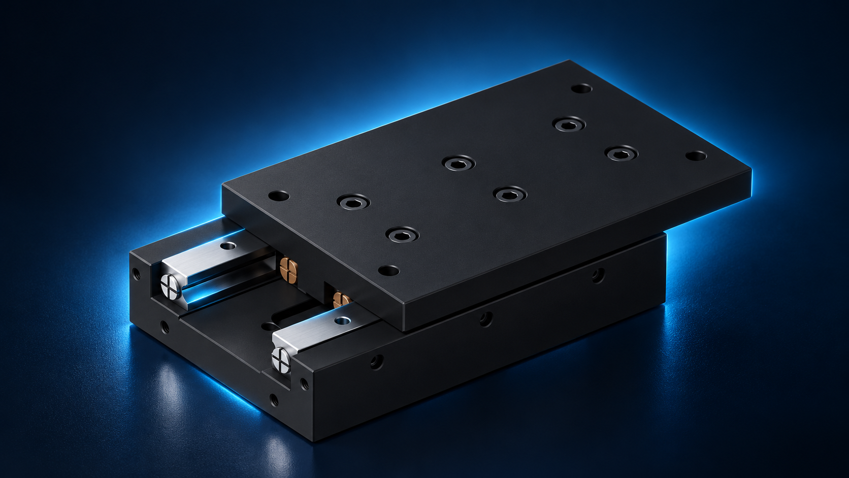
A cross-roller guide uses alternately oriented rollers between opposing raceways. A cage maintains roller spacing and arrangement. HZMotion CRU product and dimensional drawings show upper and lower bodies, guide regions on both sides and mounting interfaces. The catalog lists stroke and load information for CRU3xxx, CRU4xxx and CRU6xxx. It does not establish that every model has an anti-creep mechanism or provide a universal cage-reset procedure.
| Boundary | What it means | What to verify |
|---|---|---|
| Rated product stroke | The design travel range for the selected model | Exact model and applicable drawing revision; do not infer it from table length |
| Control working window | Programmed motion range relative to the machine reference | Software limits, homing offset, feedback and parameter revision |
| External machine limits | Sensors, stop logic and external mechanical stops | Stopping behavior, installation position, stop capacity and machine safety design |
| Internal retention or end features | Features associated with keeping guide components in position | Model-specific instructions; do not assume repeated-impact or braking duty |
The boundaries interact but serve different purposes. An untouched external stop does not establish correct internal cage position. A controller showing a position inside its limits does not rule out contact with a screw, fixture or cable. Stop attempts to extend motion when unusual resistance appears.
02 / Kinematics
Normal cage motion is different from cage creep
Consider an ideal guide with a stationary lower raceway and a translating upper raceway. Under pure rolling, the contact-point velocities match the stationary and moving surfaces. The roller center, and nominally the cage, therefore travels at half the speed of the moving raceway. A cage that changes position during a table move is not necessarily abnormal. The relationship is a kinematic model, not a field adjustment instruction.
Δxc ≈ Δxt / 2
Δxt is upper-table displacement relative to the stationary base. Δxc is nominal cage displacement relative to the same base. The model assumes rolling without slip.
Cage creep describes accumulated displacement relative to the expected cage position, rather than its normal movement during a stroke. Vibration, impact, gravity orientation, drive characteristics and slip may influence the condition. Repeated short-stroke operation is useful operating information, but short travel or a high cycle count alone does not diagnose creep.
The public CRU references reviewed do not identify a rack-and-pinion anti-creep system, automatic reset device or customer adjustment procedure. Features from a different guide design must not be assumed for CRU. Do not remove guide parts or adjust preload merely to inspect a cage.
03 / Diagnosis
Use repeatable observations to narrow the cause
| Observation | First checks | Conclusion to avoid |
|---|---|---|
| Stops at the same control coordinate without unusual resistance | Software limits, homing offset, alarms and input signals | The mechanical stroke has necessarily shortened |
| Contact or resistance appears after fitting a new fixture | Screw penetration, overhang, cable routing and guards | The cage must be the cause |
| Resistance increases after external mounting bolts are tightened | Base contact, surface condition and tightening sequence | Internal adjustment can compensate for the base |
| Visible cage position changes progressively at the same table reference | Initial condition, cycle history and identifiable visible features | The cage can be forced back based on its measured displacement alone |
| Scoring, particles, unusual noise or localized sticking | Stop operation, preserve the condition and arrange inspection | Remaining movement proves that no damage occurred |
- Preserve the operating conditionRecord load, orientation, direction, speed and the position where the symptom appears. Changing several variables at once makes the evidence harder to interpret.
- Check external boundaries firstFollow the machine isolation procedure for power and stored energy. Independently support gravity-loaded axes before any connection is released.
- Inspect visible mounting and interferenceCheck exposed fasteners, fixtures, limit switches, cables and guards. Slow inspection movement must stay within the method and range allowed by the manufacturer.
- Compare at the same referenceUse a repeatable reference on the fixed base for table and visible cage positions. Photographs taken at different table positions cannot by themselves demonstrate cage creep.
- Provide reproducible evidenceIf external causes do not explain the symptom, supply the model, drawing revision, photographs and operating conditions for service assessment. Repeatedly driving into an end is not a diagnostic method.
Compare movement resistance under consistent speed, direction, temperature and loading. Feel can reveal a change, but it is not a substitute for measurements made by an agreed method. In a driven assembly, resistance from transmission parts and seals also needs to be separated from guide behavior.
04 / Travel planning
Rated stroke is the starting point for a working window
The HZMotion catalog lists a 60 mm stroke for CRU3105. Consider a hypothetical travel-planning example: the applicable drawing confirms a rated range expressible as −30 to +30 mm about the selected center, while the process uses −20 to +20 mm. The nominal geometric margin is then 10 mm at each end. This calculation does not complete the limit design.
Swork = xmax − xmin = 40 mm
Example working window: −20 to +20 mm. Catalog total stroke: 60 mm. Both must use the same reference, with the center established by the applicable drawing or approved assembly datum.| Quantity | Example or check | Engineering meaning |
|---|---|---|
| Rated total stroke | CRU3105 catalog value: 60 mm | Applies to the listed model, not every CRU stage |
| Working window | Example: 40 mm | Determined by process position requirements |
| Nominal margin at one end | Example: 10 mm | Distance between the working window and the rated boundary |
| Stopping distance and other allowances | Verify speed, response, deceleration, tolerances, temperature and control design | The 10 mm geometric value cannot automatically cover every requirement |
List process positions, sensor-trigger positions and final stopping positions separately. The axis may continue moving after a limit signal changes. Whether an external stop must absorb an impact is a separate design question. A fixture change can also alter clearance and moment loading even when the programmed window stays the same.
05 / Inspection information
A useful record turns a symptom into an engineering question
| Item | What to record | Useful evidence |
|---|---|---|
| Product and revision | Full model, serial or batch identification, drawing revision | Identification, order record or approved drawing |
| Installation and load | Horizontal, vertical or inclined; mass, center of gravity and drive | Installation photograph and fixture drawing |
| Motion profile | Window, frequency, speed, acceleration and cycle count | Parameters and operating log |
| Onset | Initial mounting, final tightening, fixture change, collision or maintenance | Timeline and change list |
| Position and direction | Reference, symptom coordinate, direction and whether it changes with cycles | Measurements and photographs at a common reference |
| Completed checks | External contact, limits, alarms, lubrication and contamination | Actual findings rather than a generic “normal” entry |
After correction, verify the intended operating window and load. One unloaded movement is insufficient to represent the original process. Keeping before-and-after records also helps separate an installation event from a condition that develops with service.
06 / Frequently asked questions
Five checks before intervention
Does a moving cage indicate a problem?
No. Under ideal pure rolling the cage moves by approximately half the table displacement. Compare at the same table reference and distinguish normal stroke motion from accumulated displacement.
Does every CRU stage have an anti-creep mechanism?
The public CRU references do not support that claim. A feature and its use conditions must be confirmed for the exact model and drawing revision.
Can internal end screws be used as machine stops?
Not by assumption. Internal retention and external travel limitation have different duties. The machine needs an independently defined stopping and extreme-position arrangement.
Can a shortened stroke be restored by forcing the table?
Do not force or hammer the assembly or repeatedly hit its ends. Complete the external-limit and mounting checks, then have the appropriate service method confirmed.
Must a short-stroke application periodically move to both ends?
There is no universal procedure that can be applied to every CRU model. Follow written model-specific maintenance instructions; do not exceed the intended travel or strike internal end features as an attempted correction.