Published:2026-10-29 00:00:00
Updated:
Protection · Environment · Maintenance
Match the protective structure to the actual exposure
Cover selection is more than adding an outer shell. Describing dust, chips, liquids and cleaning conditions makes it possible to select a configuration that can run, drain and be maintained effectively.
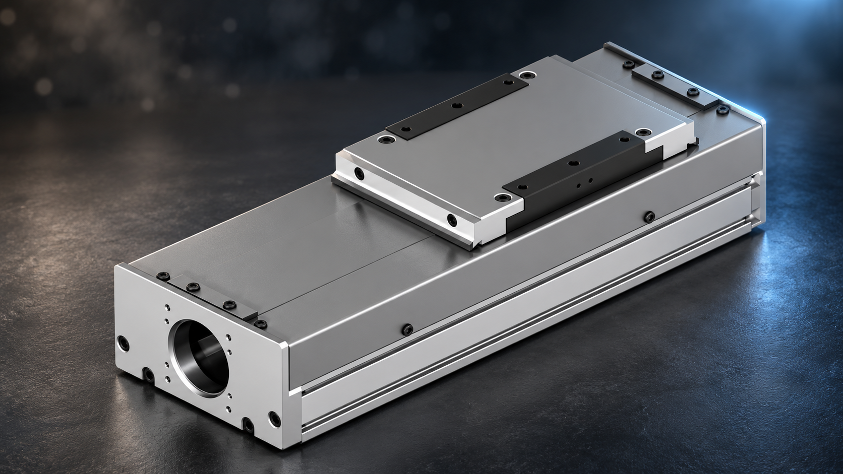
01 / Exposure
Describe the contamination path first
An actuator carrying components in an assembly area and one installed next to a drilling station can have the same payload and stroke, yet need different protection. The first may mainly encounter airborne dust. The second may receive directional chips and coolant. Selection begins with how contamination reaches the moving components.
Describe five conditions: the contaminant, particle size or liquid chemistry, direction of exposure, duration and cleaning method. Photographs of normal production and end-of-shift cleaning are more useful than a specification that says only “dusty environment.” State whether the axis is horizontal, vertical or side-mounted: orientation can turn an easy drainage path into a collection point.
| Exposure | Information to provide | Locations to examine |
|---|---|---|
| Dry dust | Particle range, concentration changes, adhesion and conductivity | Moving openings, steel-strip contact, ends and service interfaces |
| Chips | Material, shape, temperature, direction and landing area | Impact faces, folded regions, overlapping panels and chip discharge |
| Liquid splash | Chemistry, flow, direction and exposure duration | Ends, fastener openings, moving clearances and pooling locations |
| Cleaning | Wiping or washing; pressure, temperature and agent | Cover/seal compatibility, joints, drainage and drying |
| Clean environment | Particle-control target and test conditions | Wear, lubricant and particles generated by cover motion |
Keeping outside particles away from the mechanism and minimizing particles generated by the mechanism are different objectives. Water resistance, corrosion resistance and suitability for a cleanroom classification also need their own evidence. The word “enclosed” does not establish all of these properties.
Protection capability depends on the ordered configuration, approved drawing and agreed verification conditions.
02 / Catalog check
Identify the protection actually included in the order
The HZMotion linear actuator catalog describes different arrangements for TKS, TKC and HZM. Read the assembly description together with the ordering code. Options within a family can differ, and the same letter may have different meanings in different product families.
| Family / option | Structure confirmed by the catalog | Items still to confirm |
|---|---|---|
| TKS / TKS□B | Steel strip, side panels, base and end supports form the enclosure; screw and belt drives respectively | Delivered strip/panel arrangement, moving openings, orientation and exposure medium |
| TKC | Enclosing bellows are described; no protection mark means no bellows, while C includes bellows | Whether the actual order includes C, plus material, compressed space and interfaces |
| HZM + R | Telescopic protective cover | Panel material, overlap, wiping arrangement, stroke and service space |
| HZM + B | Bellows protective cover | Material compatibility, folding space, end connections and operating conditions |
| HZM without protection mark | No protective cover in this ordering field | Whether machine-level guarding is provided or a covered configuration is required |
The TKS description explains that the steel strip, side panels and related components help keep falling solids and splashing liquid out of the mechanism. It does not specify washing pressure, immersion depth or exposure duration. Direct jets, persistent pooling and cleaning chemicals therefore need separate confirmation.
TKC deserves a specific ordering check. The catalog describes bellows but also lists both “without bellows” and “with bellows” options. A protective description in the family heading is not proof that every order includes the cover. Likewise, interpret HZM R and B within the protection field rather than transferring their meanings to another series.
Catalog basis: TKC, PDF pages 185–186; TKS, pages 215–216; HZM, pages 291–292. These are PDF viewer page numbers in the Chinese catalog.
03 / Structure
Plan discharge and cleaning as well as exclusion
An effective cover keeps contamination in a location that can be cleaned. Blocking debris without providing discharge, drainage or access can leave a difficult maintenance task and allow contamination to enter during cleaning. There is no universal ranking of cover types; compare them against the exposure and available space.
| Arrangement | Application to evaluate | Design and service checks |
|---|---|---|
| Steel strip and side panels | Compact axes requiring protection from direct fallout and splash | Strip flatness, contact and guidance; do not pry up the strip to clean the mechanism |
| Bellows | Flexible coverage that extends and compresses with travel | Debris in folds, wear, compressed space and chemical compatibility; confirm hot-chip suitability |
| Telescopic cover | Overlapping panels protecting the moving region | Overlap, wiping, dents, interference and drainage; metal construction alone is not proof of water resistance |
| Machine-level enclosure | Strong exposure, multiple spray directions or a separated machining area | Intercept contamination before it reaches the axis while retaining discharge and service access |
If dry chips fall mainly from above, concentrate on landing points and removal. If coolant continually arrives from the side, follow the jet toward the ends, carriage interface and service entries. Whether a flexible cover tolerates hot chips depends on its actual materials and layers. Metal panels do not mean every joint can withstand pressure washing.
Mark three paths on the machine layout: contamination entering, contamination leaving under gravity, and maintenance access. Where they meet at a moving opening, first consider machine guards, collection trays or a different source direction. Check any added machine components over the full stroke, at stopping positions and during service.
04 / Drive allowance
Include cover resistance in the drive calculation
Bellows extension, panel sliding and steel-strip guidance can affect resistance to motion. The contribution depends on the design, travel position, speed, temperature and condition. Obtain information for the actual configuration or compare measurements under controlled conditions; do not transfer resistance values between cover types.
ΔT = Fc · p / (2π · η) Pc = Fc · v
Simplified steady-state screw-drive calculation. F_c is additional axial resistance, p is lead in m/rev, η is transmission efficiency and v is linear speed. ΔT is additional screw-shaft torque; P_c is mechanical power used to overcome the resistance.For an independent example, assume additional resistance of 20 N, a 10 mm lead, efficiency of 0.90 and speed of 0.30 m/s. The additional screw-shaft torque is approximately 0.035 N·m and mechanical power is 6 W. These are assumed calculation inputs, not test results for an HZMotion model. They show how resistance consumes drive allowance; they do not predict a temperature rise inside the cover.
| Assumed additional resistance | Additional screw-shaft torque | Mechanical power at 0.30 m/s |
|---|---|---|
| 10 N | 0.018 N·m | 3 W |
| 20 N | 0.035 N·m | 6 W |
| 40 N | 0.071 N·m | 12 W |

This equation estimates a steady-state contribution at the screw shaft. A belt drive uses the effective pulley radius and relevant efficiency; a geared axis also needs conversion to the motor shaft. Motor sizing must combine payload, acceleration, gravity and friction, and check both peak and continuous capability.
Record the current or torque trend across the full stroke at consistent load, speed and lubrication conditions. Combine this with a mechanical inspection. A current change may also come from guidance, the screw, cable carriers or controller settings, so it cannot identify a cover fault by itself. A new local resistance peak warrants inspection for interference, debris and loose connections.
05 / Installation and care
Record the conditions used for inspection
- Confirm the configuration before installationMatch the complete model, approved drawing and delivered assembly. Examine connections, strip condition and visible transit damage.
- Check the full stroke at low speedUnder safe conditions, observe both ends, compressed and extended regions, and clearance to fixtures, cables and guards. Keep clear of moving pinch points.
- Verify the actual exposure directionAgree the medium, direction and duration with the supplier. Do not substitute an unapproved pressure wash or immersion test.
- Create a condition baselineKeep photographs, motion records and the cleaning method. Use consistent conditions for subsequent comparison.
- Adapt cleaning to contaminationClean outside first and use the confirmed maintenance method. Avoid blowing dust into openings or changing the steel-strip path.
| Item | Changes to record | Response to consider |
|---|---|---|
| Steel strip / panels | Lifting, dents, scraping or uneven movement | Stop and inspect debris and interference before resuming |
| Bellows | Cracks, abnormal folding, loose ends or debris | Recheck material/environment suitability and the repair or replacement method |
| Discharge / drainage | Accumulation, return flow or cleaning residue | Improve machine-level collection and cleaning paths |
| Motion | Starting torque, resistance or current trend | Review position, temperature and lubrication before assigning a cause |
| Access | Inspection requires extensive disassembly | Provide practical service space and removable guarding in the layout |
Set inspection frequency from exposure and operating time. Shorter initial observation intervals can establish how quickly debris accumulates before a routine interval is chosen. Cleaning the cover does not replace screw and guide lubrication; see linear actuator lubrication and maintenance.
06 / Questions
Protective cover selection FAQ
Does “enclosed” mean the axis can be washed directly?
The name alone is insufficient. Confirm openings, ends, chemical compatibility and test conditions, including pressure, temperature, distance and exposure duration.
Are bellows always suitable for metal chips?
Suitability depends on chip temperature, shape, impact direction and the actual cover material. Sharp or hot chips may require additional guarding or a specifically confirmed configuration.
How does dust protection differ from cleanroom suitability?
Dust protection concerns outside contamination entering. Cleanroom evaluation also concerns particles, lubricants and material emissions generated by the mechanism itself.
Should the drive be checked after adding a cover?
Yes. Confirm whether added resistance, moving mass and extension/compression space affect the original design. The magnitude depends on the configuration and operating conditions.
What information helps a selection review?
Provide the full model or target stroke, orientation, contaminant photographs and properties, exposure direction, cleaning method, speed and service space. Specify acceptance conditions for any special protection requirement.