Published:2026-11-10 00:00:00
Updated:
Buckling · Compressed span · Axial load
Let the load path define the calculation
Different nut positions can produce different compressed lengths and support reactions. Relating axial internal force, lateral restraint and calculation length makes the stability assessment explicit and reviewable.
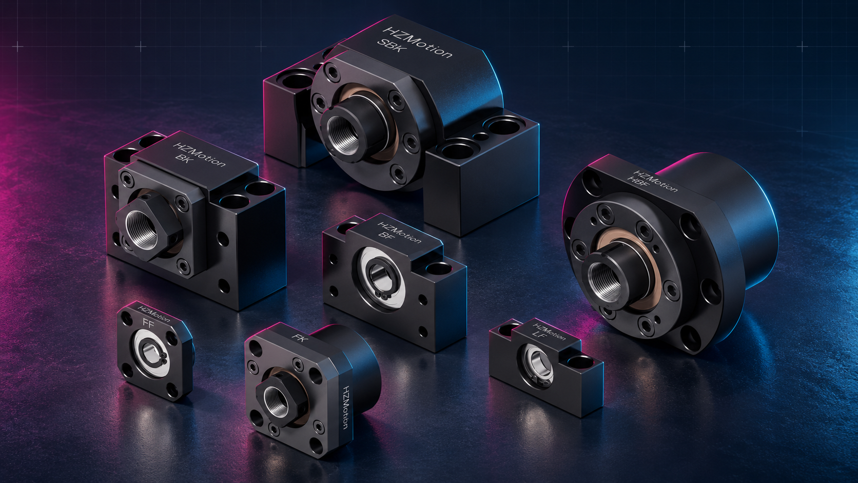
01 / Load path
Identify the segment in compression first
Thrust in a long-travel axis passes through the nut, screw, support bearings and machine base. Bearing-load calculations assess the support components. A buckling check asks whether a slender screw segment can transmit compression while remaining stable. Keeping those questions separate helps identify whether the design needs a different shaft section, support layout or support assembly.
Begin with an axial free-body diagram at the nut position of interest, not with the overall screw length. Mark the force applied by the nut to the screw, the reactions at the axial locating ends and the direction of load transfer. Determine which segments are in tension and which are in compression. Workpiece weight alone is not the screw compression load: orientation, acceleration and process-force direction all matter.
| Axial arrangement | How to identify internal axial force | Boundary still to establish |
|---|---|---|
| Axial location at the left end only | A nut force pushing the screw toward the left end compresses the left segment; reversing it can put that segment in tension | Radial support on the other side can still affect lateral deformation |
| Axial location at both ends | The nut force is shared according to the actual stiffness of the two paths | Initial tension, temperature and support flexibility change the net tensile/compressive state |
| Multiple supports or a special layout | Build a segmented model from the actual load and lateral restraints | Intermediate support effectiveness, moving position and joint stiffness remain relevant |
Directions here refer to the force exerted by the nut on the screw. The screw exerts the opposite force on the nut and carriage. Stating that convention prevents travel direction from being mistaken for compression direction. For reversing motion, include both directions and the relevant acceleration and deceleration phases.
The compressed segment and the effective buckling length are not automatically the same number. An adjacent unloaded shaft segment, the lateral restraint supplied through the nut and guides, and the angular flexibility of a support all affect how the segment ends can move. A real screw segment may be treated as an isolated column only when the chosen boundary approximation is justified.
02 / Model boundaries
Represent ideal end restraint through effective length
Pcr = π²EI / (KL)²; I = πde⁴ / 64
E in N/mm²; I in mm⁴; L is the geometric length of the modeled segment in mm; K is the effective-length factor; P_cr is in N. d_e is the equivalent solid-rod diameter used in this example.Euler theory describes elastic instability of an ideal slender, initially straight column under centered compression. The section and material model must be defined, the lateral restraints must be represented appropriately, and the result must remain within the applicable elastic slender-column range. A short stocky shaft, eccentric loading, initial curvature, stepped geometry or flexible connections can require a different or more detailed analysis.
| Ideal bending boundary | K | Meaning within the ideal model |
|---|---|---|
| Pinned–pinned | 1.0 | Lateral movement is restrained at both ends; end rotation is free |
| Fixed–free | 2.0 | One end restrains lateral movement and rotation; the other has no lateral restraint |
| Fixed–pinned | About 0.699 | One end restrains movement and rotation; the other restrains lateral movement only |
| Fixed–fixed | 0.5 | Both ends ideally restrain lateral movement and rotation |
The words fixed and pinned in this table describe bending boundary conditions. They cannot be assigned from the commercial names “fixed end” and “support end” alone. The bearing arrangement, bearing spacing, housing, mounting joints and restraint through the nut must provide the assumed behavior. Where that is uncertain, use the product’s engineering method or a suitable beam-column model rather than selecting the coefficient that gives the highest result.
A real screw has raceways and machined end sections. Obtain the section properties from the supplier’s method, root diameter and critical geometry. The d_e used here defines an independent equivalent circular rod; it does not imply that nominal screw diameter equals root diameter. If a product formula already defines a section approximation, end coefficient and safety reduction, use those definitions together.
Buckling load is expressed in force units; critical speed is expressed in rpm. Both depend on length and support, but they have different equations and coefficients. Coefficients for rotational critical-speed calculations do not belong in this column equation.
03 / Independent example
See how length changes the stability check
Take an ideal pinned–pinned equivalent solid rod with E = 210,000 N/mm², d_e = 16 mm and K = 1. Compare modeled compression lengths of 600, 900 and 1,200 mm. To distinguish the theoretical critical load from a screening value, choose an illustrative divisor γ = 2 and compare P_cr/γ with an assumed compressive force of 4,000 N. This γ is not a universal requirement for HZMotion products or machine structures.
I = 3,216.99 mm⁴; Pscreen = Pcr / γ
P_screen is only the screening value defined for this example. Before using a product’s stated permissible load, establish whether its calculation already includes a safety reduction.| Model length L | Theoretical P_cr | Illustrative P_cr/2 | Screening value / 4 kN |
|---|---|---|---|
| 600 mm | 18.52 kN | 9.26 kN | 2.32 |
| 900 mm | 8.23 kN | 4.12 kN | 1.03 |
| 1,200 mm | 4.63 kN | 2.32 kN | 0.58 |

Doubling length from 600 to 1,200 mm reduces the theoretical critical load to one quarter. At 900 mm the ratio is approximately 1.03: under these ideal assumptions and this chosen reduction, the screening value is only slightly above the stated load. That is not acceptance of a real machine. A more flexible boundary, eccentric force or different section requires the calculation to be revisited.
Within the same model, P_cr varies with d_e to the fourth power. Section selection is therefore sensitive, but a larger shaft also affects rotating inertia, shaft-end machining, bearings and the drive. Compare the complete solution rather than increasing diameter until one equation gives an attractive answer. A reduction in calculation length likewise needs a real change in support or travel conditions.
04 / Separate checks
Check stability, material, contact and connections
σax = Fc / A; A = πde²/4
For the example, A = 201.06 mm². At F_c = 4,000 N, average axial compression stress is about 19.9 N/mm². This is not a material allowable stress.A modest average stress does not establish buckling stability: a slender member can become unstable before its material reaches yield. Conversely, Euler theory can predict a high load for a short segment, while material strength, raceway contact, a shoulder or a connection governs first. Use strength criteria appropriate to the material, heat treatment and geometry, and establish whether the Euler model remains applicable.
| Check | Main inputs | What cannot substitute for it |
|---|---|---|
| Screw compression stability | Maximum net compression, position, section and lateral boundaries | Bearing dynamic load rating or screw critical speed |
| Shaft section and transitions | Net section, material condition, axial force and concurrent bending/torsion | Average stress calculated from nominal diameter alone |
| Ball screw nut contact | Model ratings, actual load spectrum, preload and static requirements | Buckling load of an equivalent solid rod |
| Supports and mounting joints | Bearing, shoulder, locknut, housing and machine-base reactions | One bearing rating or the feel of a tightened fastener |
With two axial locating ends and thermal changes, calculate the actual net internal force before checking stability. Initial stretching can keep a segment in tension under some conditions. Heating can reduce that tension; whether compression develops depends on relative thermal growth of the screw and mounting base and on support flexibility. Do not simply add initial tensile preload to every segment’s compressive load.
Place the checks beside one another in the duty record, retaining their load direction, position, duration and calculation method. Only comparable quantities can identify the governing limit. Ratings with different definitions should not be arranged in a column and reduced to the smallest numerical value without first relating each to its actual duty.
05 / Design information
Check the unfavorable combinations along travel
The governing location is not always a particular travel endpoint. It depends on which segment is compressed at that instant, the compression force and the restraint. A segment may become longer during extension while the process force occurs only on return. Combining the longest span with the largest force can create a condition that never occurs; omitting reversal acceleration or vertical holding loads can overlook one that does.
- Confirm structure and referencesProvide the complete screw specification, shaft-end drawing, root diameter or supplier section data, support installation and nut travel range.
- List the duty casesRecord external force, acceleration, gravity direction, initial tension and temperature at the relevant positions.
- Resolve forces and boundariesSeparate tension and compression segments, determine support reactions, then establish lateral restraint. Use an approved segmented or numerical model where necessary.
- Check each limit separatelyAssess stability, section strength, nut contact, support life and joint capacity with the corresponding method.
- Preserve the conditionsRecord permitted load–position combinations, model assumptions, design margins and outstanding validation items.
The HZMotion support-unit catalog helps identify family geometry, bearing configurations and mounting relationships. A housing model by itself cannot define the buckling load of a complete screw. Review the support-unit catalog together with the actual screw, nut and machine-base drawings. For a complete actuator, first confirm the manufacturer’s axial-load and operating limits for the selected size and stroke.
Commissioning can verify assembly behavior, displacement and temperature, but it should not seek a working-load limit by increasing force until the shaft bends. Complete the stability analysis during design. Agree the validation load and method in advance and keep testing within the approved operating envelope.
If the end restraint cannot yet be established, record that missing evidence explicitly. Photos can explain the arrangement, but the calculation also needs dimensions and mechanical constraints. That distinction helps a supplier review focus on the information that actually controls the result.
06 / Questions
Four boundaries in a buckling assessment
Does a screw in tension require the same column calculation?
Pure axial tension does not produce the same Euler compression-buckling mode. Material, contact, shaft-end and connection limits still apply. Check any separate compression cases caused by reversal, temperature or other operating conditions.
Can working stroke be used directly as the calculation length?
No. Stroke describes carriage travel. The calculation length follows the compressed segment and its lateral boundary in the selected load case. Mark that definition on the installation drawing and update it with nut position.
Do two fixed-end support units automatically justify K = 0.5?
No. K = 0.5 represents ideal fixed–fixed bending restraint. Whether the bearings, housings, connections and force-application location provide that condition must be established from the structure.
Is γ = 2 the standard for every model?
No. It is used here only to distinguish a theoretical critical load from a screening value. Use the target product’s method, applicable design requirements and confirmed duty when choosing actual design factors and allowable loads.