Published:2026-10-10 16:00:00
Ball screw support units · Loads and life
Build a bearing load spectrum from the duty cycle
Support-unit life assessment connects machine thrust, bearing arrangement, speed and operating time. Establish the load path first, then check fatigue life, static capacity and structural limits separately to produce a useful selection result.

01 / Rating definitions
Dynamic ratings, static ratings and structural limits
Load values in a catalog may describe different components and criteria. Substituting a support housing's allowable axial load for a bearing's dynamic rating changes the meaning of the life equation. Identify the source, units and applicable bearing or assembly before calculating.
| Parameter | Engineering meaning | Application |
|---|---|---|
| Dynamic load rating C | The basic dynamic load rating of the specified bearing or bearing set, under its stated rating definition. | Use with equivalent dynamic load P for that same calculation object to determine basic rating life. |
| Static load rating C₀ | A bearing rating established using the applicable static-load criterion. | Use with equivalent static load P₀ to check static safety factor s₀ = C₀ / P₀ against the applicable requirement. |
| Allowable axial load | The axial capacity limit of a support unit or connection under specified conditions. | Check peak external loads and structural capacity. This value does not replace C or C₀. |
| Axial stiffness and permissible speed | Limits on displacement and operation, affected by configuration, preload and lubrication. | Check accuracy, temperature rise and speed separately; the life equation does not establish compliance. |
For example, the SBK specification pages in the HZMotion support-unit catalog describe the listed allowable axial load as the maximum axial force supported by the housing structure. Use that column for the corresponding structural check. Obtain C separately for the actual bearing configuration.
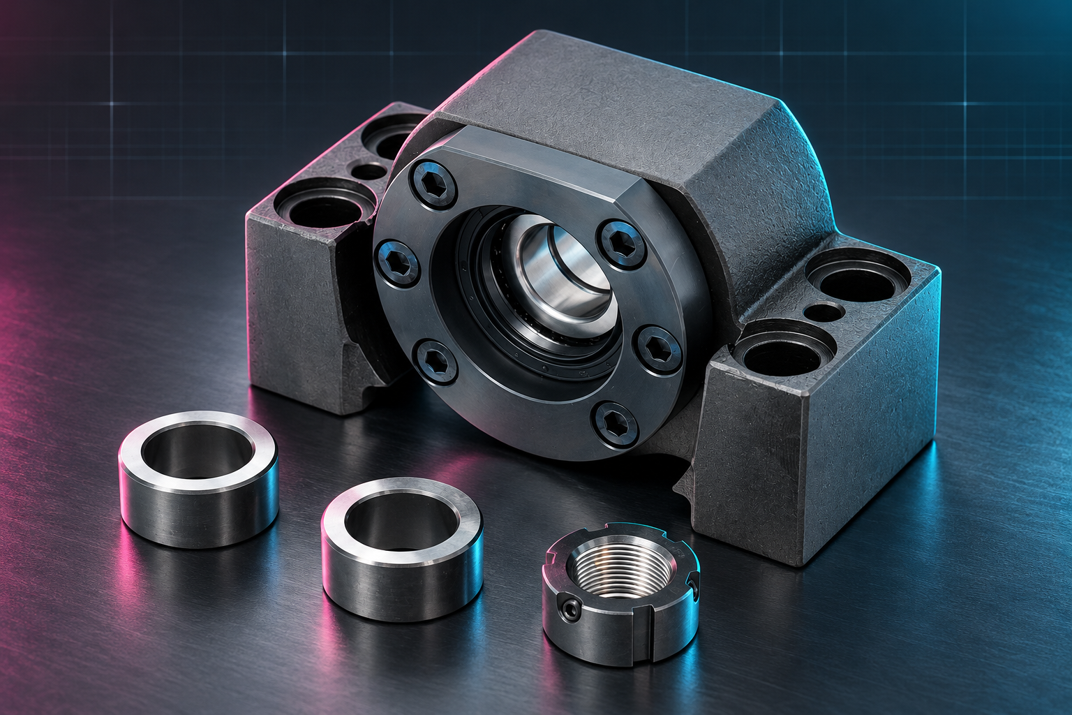
Check the specific model within SBK, SBK-U, WBK, FBSA and MBK families individually. DF, DB, DFD and DFF arrangements have different load and stiffness relationships; see the heavy-duty fixed-end bearing arrangement guide for selection context.
02 / Duty-cycle loads
Translate machine loads into bearing loads
Trace the actual load path: payload and process forces act on the moving assembly, pass through the ball nut and screw shaft, and reach the frame through the fixed-end bearings and housing. Gravity components differ between horizontal and vertical axes. Restraint at both ends, thermal growth and screw pretension can also change support reactions. Payload mass alone is not the fixed-end bearing's P.
- Define a complete cycleList acceleration, constant-speed travel, deceleration, reversal and dwell. Record duration, speed profile, process forces and travel direction.
- Model external loadsInclude gravity, inertia, process forces, friction and other known actions according to mounting orientation. Solve support reactions and document axial restraint at the fixed and supported ends.
- Determine internal bearing loadsUse the applicable bearing method to obtain equivalent dynamic load Pᵢ and static load P₀, accounting for contact angle, arrangement, preload and load direction. Do not assume equal sharing between bearings.
- Keep peaks and revolutionsPeak loads support static and structural checks. Loads and revolutions during rotation support fatigue calculations. Retain the originating load case for both.
Pᵢ is a nonnegative equivalent dynamic load. For reciprocating motion, assess the bearings that carry each direction and accumulate the absolute number of revolutions. Opposite directions do not cancel fatigue loading. Multiplying a single bearing's C by the number of bearings does not establish the set rating.
03 / Calculation method
Revolution-weighted equivalent dynamic load
For ball bearings, the following relations apply to a segmented duty cycle after the bearing loads have been established and the basic rating life model selected. Pᵢ and speed are treated as constant within each segment. Subdivide continuously varying conditions or integrate the combined load and speed history.
| Quantity | Relation | Units and conditions |
|---|---|---|
| Segment revolutions | Nᵢ = |nᵢ| × tᵢ / 60 | nᵢ in r/min, tᵢ in seconds, Nᵢ in revolutions. For variable speed, use ∫|n(t)|dt / 60. |
| Equivalent dynamic load | Peq = [Σ(Pᵢ³Nᵢ) / ΣNᵢ]1/3 | Use consistent load units. Weight by revolutions, rather than time alone. |
| Basic rating life | L₁₀ = (C / Peq)³ | L₁₀ is in millions of revolutions. C and Peq refer to the same bearing or rated set and use identical units. |
| Cycle-average speed | n̄ = 60 × ΣNᵢ / T | T is the complete cycle duration in seconds. Including dwell makes the converted hours include that dwell. |
| Conversion to hours | L₁₀h = 10⁶ × L₁₀ / (60 × n̄) | The same cycle proportions must repeat; n̄ must be greater than zero. |
ISO 281 defines basic rating life at 90% reliability. This is a statistical measure under specified conditions, not a guaranteed service duration for every unit. Lubrication, contamination and reliability requirements involve further adjustments; basic fatigue life also does not cover every failure mechanism, such as wear or corrosion.
The HZMotion support-unit catalog provides the constant-condition ball-bearing life equation in hours. The segmented calculation above applies the same fatigue model to a load spectrum. Roller bearings, dedicated bearing-set models and linear guides with distance-based ratings require their corresponding calculation methods.
04 / Worked example
A 100-second cycle and its life conversion
Assumptions: the calculation object is one ball bearing with an assumed C of 20 kN. Each Pᵢ below already represents the bearing loading and preload effects for that condition. Rotating segments use constant values for illustration; real calculations must include acceleration transitions omitted here. These are teaching inputs, not specifications for an HZMotion model.
| Segment | Pᵢ / kN | |nᵢ| / r/min | tᵢ / s | Nᵢ / rev |
|---|---|---|---|---|
| Rotation 1 | 4 | 600 | 20 | 200 |
| Rotation 2 | 2 | 1,200 | 40 | 800 |
| Rotation 3 | 6 | 300 | 20 | 100 |
| Dwell | Separate static check | 0 | 20 | 0 |
| Cycle total | — | — | 100 | 1,100 |

The cubic weighted sum is 4³ × 200 + 2³ × 800 + 6³ × 100 = 40,800 kN³·rev. Therefore Peq = (40,800 / 1,100)1/3 ≈ 3.335 kN.
| Result | Calculated value | Interpretation |
|---|---|---|
| Basic rating life L₁₀ | About 215.7 million revolutions | Approximately 2.157 × 10⁸ revolutions, calculated before rounding Peq. |
| Cycle-average speed n̄ | 660 r/min | 60 × 1,100 / 100; duration includes the 20-second dwell. |
| Cycle-equivalent L₁₀h | About 5,447 h | Repeated operation of this 100-second cycle, with dwell included. |
The 6 kN segment accounts for only 100 revolutions, but its cubic weighted term is 21,600, approximately 52.9% of the total. Retain such high-load segments rather than representing the cycle with a simple average thrust or only its longest stage.

Dwell contributes no rotating revolutions, but holding loads, indentation, vibration-related fretting and lubrication still need assessment. A stationary application or one dominated by small oscillations should not be assessed by directly applying this example's revolution-to-hour conversion.
05 / Engineering checks
Assess the complete support assembly
- Static loads and peak conditionsDetermine P₀ for the actual bearing configuration and apply the relevant static safety-factor requirement. Check maximum axial loads, emergency stops and impact cases. Document any application factor and avoid counting the same allowance twice.
- Structure and connectionsCheck the load path through shaft shoulders, shaft-end threads, locknuts, covers, housing, mounting bolts and machine base. Bearing ratings do not establish the capacity of these connections.
- Stiffness and thermal behaviorCheck axial displacement, positioning targets, preload, permissible speed and thermal restraint. A preload change requires reassessment of internal loads and temperature rise.
- Lubrication and operating verificationSpecify lubrication, sealing and maintenance conditions. Record loaded-test temperature, noise, axial displacement, starting torque and running resistance. Combine the calculation with verification of the assembled system.
Use the support-unit installation and acceptance checklist for assembly checks. Meeting a fatigue-life target does not automatically satisfy displacement or temperature requirements.
06 / Selection inputs
Document the duty cycle and configuration
| Input group | Information to provide | Purpose |
|---|---|---|
| Mechanical arrangement | Horizontal or vertical mounting, shaft-end drawing, support span, fixed/floating relationship and pretension requirements. | Establish load paths and thermal constraints. |
| Cycle data | External loads, directions, speed profiles, durations, reversal frequency, dwell and emergency-stop cases. | Build the fatigue spectrum and peak-load cases. |
| Bearing configuration | Full support-unit model, bearing arrangement, preload and the source and scope of C and C₀. | Keep individual-bearing and set ratings distinct. |
| Operating environment | Temperature range, contamination, lubrication method, relubrication access and maintenance requirements. | Assess operating conditions and necessary life adjustments. |
| Acceptance targets | Target life and reliability, axial displacement, temperature rise, accuracy and operating test method. | Make the selection conclusion reproducible. |
07 / FAQ
Calculation and application notes
Can the catalog's allowable axial load be used as C?
Check its definition first. If it is a housing structural limit, use it for that structural check. C in the life equation must be the basic dynamic rating of the actual bearing or rated set.
Is an average load enough when speed varies?
Generally, no. The segmented ball-bearing model weights the cube of each equivalent load by its corresponding revolutions. Subdivide or integrate the joint history when load and speed vary together.
How should the lives of two bearings be combined?
Determine internal loading from the arrangement, preload and load direction, then use an applicable bearing-set assessment. Neither adding individual C values nor adding individual lives establishes assembly life.
Does a longer dwell improve support-unit life?
It changes the cycle hours converted from revolutions, but does not remove static, fretting, lubrication or environmental effects. Assess rotating fatigue and dwell conditions together.
Can basic rating life directly set a maintenance interval?
No. Maintenance also depends on lubrication, sealing, contamination, temperature and inspection history. Set intervals through the equipment's maintenance plan.