Published:2026-09-02 09:00:00
Heavy-duty fixed-end bearing arrangements
Heavy duty is not “more bearing rows.” It is a load-direction, rigidity and thermal design.
DF, DB, DFD and DFF change more than row count. The arrangement changes capacity by direction, axial rigidity, preload, starting torque, heat and alignment sensitivity. Map the load directions and duty first, then select the arrangement and housing family.
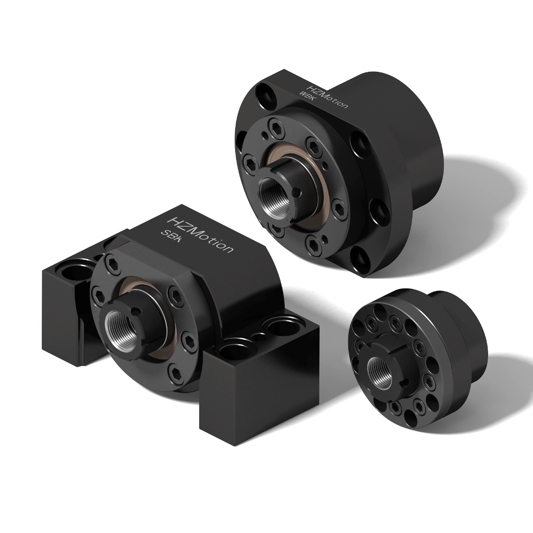
01 / Load map
Do not start from an arrangement code—map both axial directions first
| Duty information | Minimum input | Why it changes the arrangement |
|---|---|---|
| Load direction | Peak in both directions, duration and reversal frequency | Determines symmetric capacity versus extra rows in one dominant direction |
| Duty cycle | Acceleration, cutting, hold, return and dwell fractions | Peak controls structure; repeated load and time control life and heat |
| Speed | Maximum/common speed and acceleration frequency | Rows, preload, seals and lubrication affect loss and limiting speed |
| External moment | Load offset, guide span, base and nut-bracket rigidity | Separates true axial load from parasitic moment caused by geometry |
| Thermal environment | Ambient, continuous time, cooling and permitted drift | High-preload multi-row sets can heat faster; fixed-fixed systems couple growth and preload |
Code boundary: DF and DB identify contact-line orientation; DFD and DFF are multi-row combinations. The letters alone do not provide ratings. Use the complete HZMotion model and current technical manual.
02 / Four arrangements
“Heavy duty” can still mean different load directions and alignment sensitivity
| Arrangement | Typical meaning | Better fit | Verify together |
|---|---|---|---|
| DF, face-to-face | Two rows provide general bidirectional axial support; shorter effective load-center span | Similar loads in both directions with a balance of envelope and installation tolerance | Both direction ratings, preload, speed and housing rigidity |
| DB, back-to-back | Two rows spread outward; normally a wider load-center span and greater moment rigidity | Higher moment rigidity where base, shaft-end geometry and alignment are controlled | Misalignment sensitivity, thermal differential, fits and model availability |
| DFD, three rows | Two rows support one direction and one row the opposite direction | A clear dominant cutting/pressing direction with smaller return load | Installation orientation and the weaker reverse direction |
| DFF, four rows | Two rows in each direction create symmetric reinforcement | High load and axial rigidity in both directions | Starting torque, temperature, width, cost, speed and lubrication |
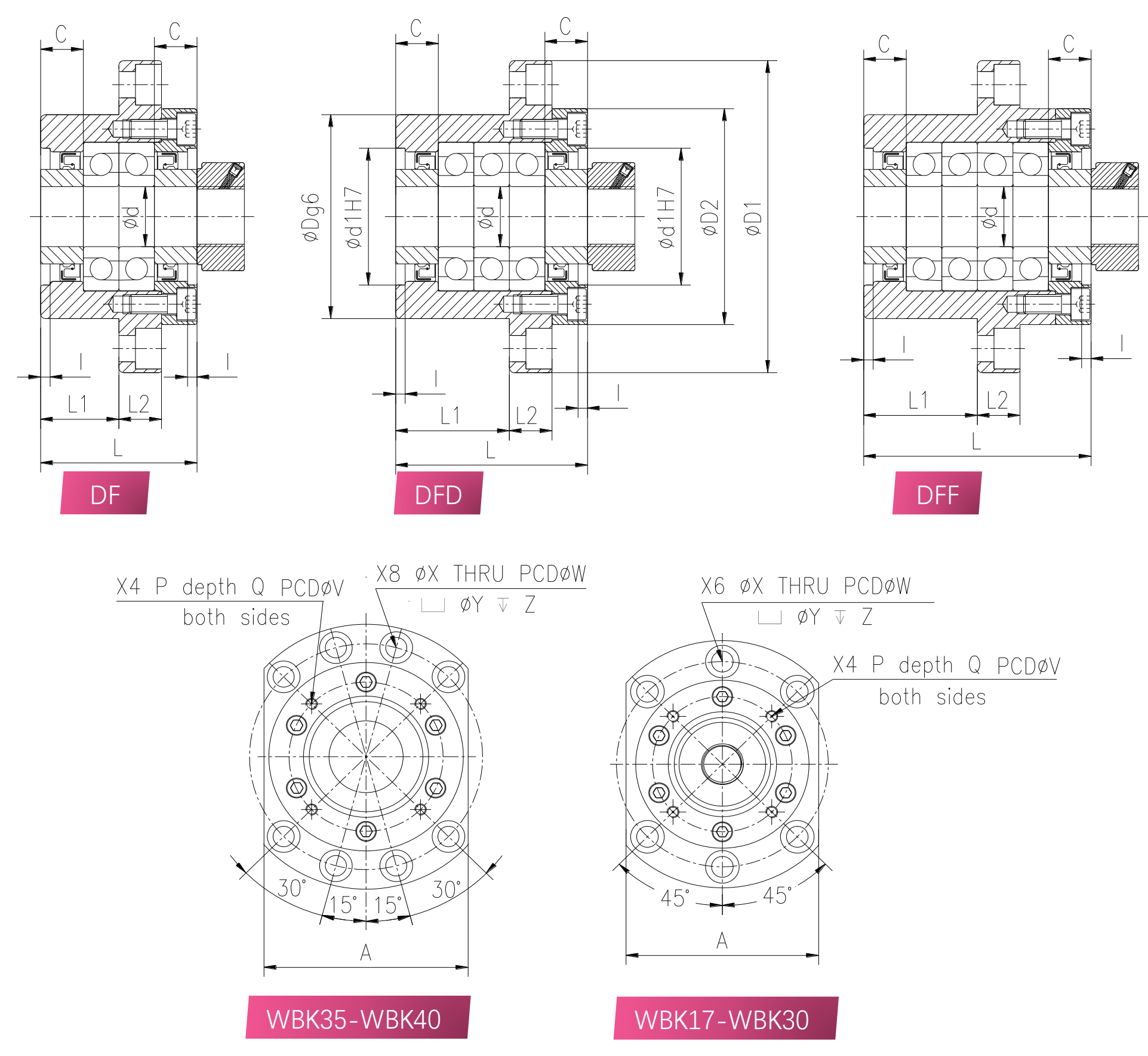
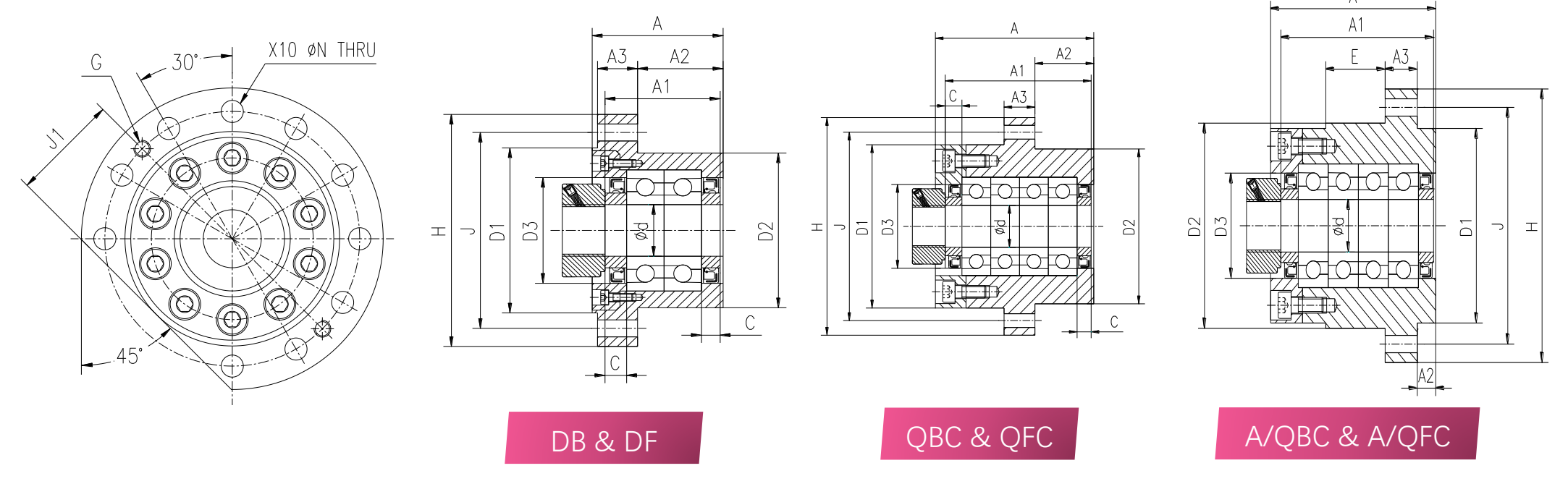
03 / HZMotion manual data
When the arrangement changes within one WBK size, verify both the load boundary and speed
The table below comes directly from the current HZMotion Ball Screw Support Units technical manual. Models and maximum axial loads are listed on page 24; bearing maximum speeds are listed on page 3. WBK25, WBK30, WBK35 and WBK40 use 60° angular-contact thrust bearings, with the preload level identified as High in the manual.
| HZMotion WBK size | DF model / max axial load | DFD model / max axial load | DFF model / max axial load | Bearing max speed |
|---|---|---|---|---|
| WBK25 | WBK25DF · 2752 kgf | WBK25DFD · 5539 kgf | WBK25DFF · 5539 kgf | 4500 r/min |
| WBK30 | WBK30DF · 2922 kgf | WBK30DFD · 5844 kgf | WBK30DFF · 5844 kgf | 4300 r/min |
| WBK35 | WBK35DF · 3398 kgf | WBK35DFD · 6769 kgf | WBK35DFF · 6769 kgf | 3600 r/min |
| WBK40 | WBK40DF · 3534 kgf | WBK40DFD · 7068 kgf | WBK40DFF · 7068 kgf | 3600 r/min |
How to read this table: for the same bearing size, the manual lists a higher maximum axial load for DFD/DFF than for DF. It does not split that value into normal and opposite directions, and it does not publish numerical axial rigidity or friction torque here. Arrangement direction and usable capability must still be checked against the complete model, bearing detail, mounting orientation and load spectrum. Maximum axial load is a structural boundary, not an average operating load or a fatigue-life load.
04 / Rigidity and deflection
Catalog bearing rigidity is not complete feed-axis rigidity
- δ
- axial elastic displacement
- Fa
- axial load in the current condition
- ksys
- combined bearing, screw, housing, bracket, joint and base rigidity
- Bearing
- arrangement, preload and bearing axial rigidity
- Screw
- effective length, diameter, tension/compression and temperature
- Joints
- housing, nut bracket, bolted interfaces and local base deformation
If the base, joint or long screw dominates system compliance, replacing DF with DFF will not improve machine positioning in proportion to the bearing catalog number. Build the compliance budget first.
05 / Starting torque and heat
The cost of “more rigid” appears in motor torque and thermal balance
- Mf
- assembly friction torque, affected by starting state, seals, lubrication and temperature
- n
- screw speed in r/min
- Ploss
- loss that is mainly converted to heat and must leave through the housing/environment
| Boundary often missed | Engineering effect | How to verify |
|---|---|---|
| Starting torque is not steady torque | Cold grease, seals and dwell can change the starting peak | Check motor start margin, low-speed stability and hot operation separately |
| More preload normally means more heat | Temperature can become the limit before static capacity at continuous high speed | Use model speed, duty and supplier friction data |
| Fixed-fixed couples thermal growth | Screw growth and end-to-end temperature difference change internal load | Review pretension, cooling, base and both housing temperature trends |
| Maximum axial load is not a life load | A structural limit cannot be substituted directly into fatigue life | Use supplier equivalent load, dynamic rating and life method |
The current HZMotion manual gives approximately 20% of maximum axial load as a quick average-load life guideline. It is not a universal cross-brand life formula; formal review still needs dynamic rating, equivalent load, speed and duty.
06 / HZMotion heavy-duty families
Filter the mounting interface first, then lock the arrangement and complete model
| Family | Typical arrangements in current drawings | Architecture | Selection reminder |
|---|---|---|---|
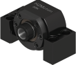
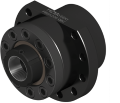
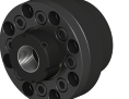
| WBK | DF, DFD, DFF | Axial/end-face-mounted heavy fixed end | Configuration changes row count and length; verify suffix and shaft-end length |
| SBK / SBK-U | DF, DFD | Block-type heavy fixed end | DFD is directional; orient the reinforced direction with the dominant load |
| FBSA | DB, DF and QBC/QFC multi-row options | Flanged large-size heavy fixed end | Do not treat every four-row option as the same arrangement; verify width and heat |
| MBK | DF, DFF | Compact heavy fixed end | When increasing bidirectional capacity in a small envelope, still check torque and cooling |
07 / Seven selection steps
Place the arrangement code inside the full engineering workflow
- Build a two-direction load spectrumList peaks, duration, return load, shock, reversals and safety conditions.
- Define the support architectureFixed-supported, fixed-fixed or pretensioned, including critical speed and thermal growth.
- Filter the housing familyUse shaft-end drawing, center height, holes, envelope and maintenance direction.
- Choose arrangement by directionStart from DF for general bidirectional duty; assess DFD for a dominant direction, DFF for two heavy directions and DB only where the model and geometry support it.
- Verify rigidity and lifeUse both direction ratings, dynamic rating, preload, rigidity and supplier life method—not only maximum axial load.
- Check motor and thermal marginInclude starting torque, steady friction, speed, duty, lubrication, seals and cooling.
- Freeze the complete model and acceptanceConfirm orientation, accuracy, bearing detail, shaft-end drawing and locking, then establish runout, clearance, temperature and current baselines.
08 / Common mistakes
Comparing maximum axial load alone can produce a rigid but incorrect axis
It raises bidirectional capability, but also preload, torque, heat, width and cost.
The strong and weak directions differ; orientation belongs on the drawing and process.
Similar housings can carry different rows, classes and preload.
Fatigue life needs equivalent load, dynamic rating, speed and cycle duty.
A stiffer bearing cannot correct compliance dominated by a long screw or weak joint.
A static-load-compliant multi-row set may still fail motor-margin or continuous-temperature checks.
09 / Quick answers
Heavy-duty arrangement FAQ
Is DFD always better than DF?
No. It fits a clear dominant direction. If reverse load is also high, the weaker direction can govern, while friction, width and cost rise.
Is DB always more rigid than DF?
DB normally has a wider load-center span and greater moment rigidity, but is more sensitive to geometry and temperature. Axial rigidity and ratings remain model-specific.
Can DFF halve axial deflection?
Not directly. Bearing rigidity is only one element in series with the screw, housing, joints and base.
Is a life calculation required if maximum axial load passes?
Yes. Maximum permissible load is a boundary check, not cyclic fatigue life. Use the load spectrum, equivalent load, dynamic rating and speed.
Why can multi-row arrangements run hotter?
More loaded rows and higher preload normally increase friction torque. At the same speed this raises loss, while seals, grease and cooling affect the result.