Published:2026-08-27 09:30:00
XY/XYZ Multi-Axis Platform Design
Good single-axis specifications do not guarantee accuracy at the point of interest
Upper axes, tooling and payload become moved load for the lower axis. Pitch, yaw and straightness are magnified by the offset to the working point. Start with the POI and coordinate frame, then define axis order, stack height, interfaces, metrology and acceptance.
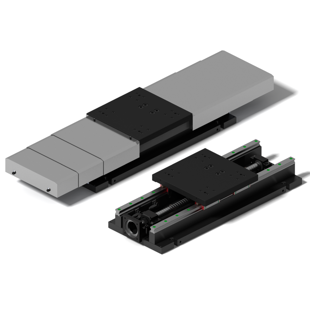
01 / POI and coordinate frame
Multi-axis accuracy belongs at the camera focus, tool tip, probe or fixture center
The same platform can show different errors at the table surface and at an elevated camera focus, tool tip, probe or fixture center. Define the machine frame, POI, full work envelope, payload center, process force, motion profile, cable state, temperature and test directions before comparing specifications.
Place the measurement target close to the actual process point, not only at a convenient table-surface location.
Upper axes, adapters, tooling, payload and cables all enter the lower-axis mass and moment calculation.
Define corners, directions, cold/hot state, representative load and speed rather than one center point.
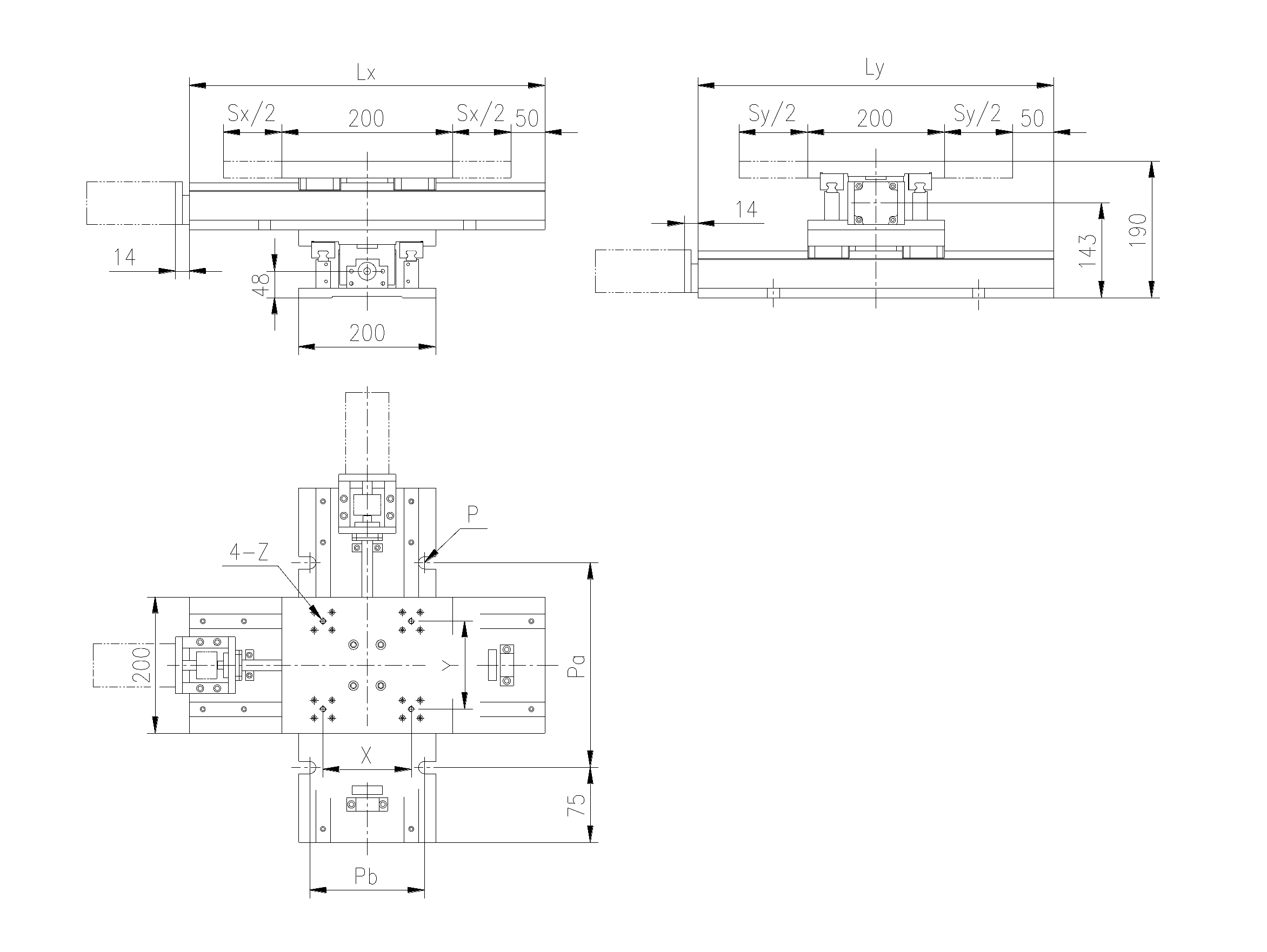
02 / Abbe error
A small angular error becomes linear error when multiplied by POI height
When the feedback or nominal motion line does not pass through the POI, pitch or yaw creates additional displacement. For one plane and a small angle:
- d
- The Abbe offset, not axis travel.
- θ
- The pitch or yaw error corresponding to the offset direction.
- 3D form
- For small rotation, Δr ≈ φ × r; sign follows the coordinate convention.
- Scale example
- d = 200 mm and θ = 50 µrad gives about 10 µm; this is not an HZMotion tolerance.
Reduce geometric amplification
Lower the POI, shorten overhang, move feedback closer to the POI and reduce guide pitch/yaw. Encoder resolution alone does not remove Abbe error.
Measure at the POI
If the process occurs at an elevated focus or tool, put the acceptance target there. Table-surface data is only a local reference.
03 / Axis squareness
Accurate X and Y axes can still form a skewed XY coordinate system
Squareness is the departure of two actual motion directions from the ideal 90° relationship; it is not an individual-axis repeatability figure. For angular deviation ε and travel L:
- L
- The evaluated motion length.
- ε
- Departure of the two axis directions from the ideal orthogonal relationship.
- Coupling
- Straightness, pitch/yaw, line fitting and test location affect the result.
- Acceptance
- Fix position, direction, sign, fitting method and work zone.
Passing single-axis repeatability does not prove an XY trajectory: diagonal, circular and contour motion also depend on squareness, following, reversal and settling.
04 / Stack rigidity and axis order
The lower axis moves everything above it—not only the workpiece
| Include on the lower axis | Why it matters | Common omission |
|---|---|---|
| Upper axes and adapter plates | Increase moved mass, inertia and acceleration force | Entering workpiece mass only |
| Tooling, payload and process force | Create offset load and overturning moments | No center-of-gravity coordinates |
| Moving cables and chains | Create travel-dependent force and moment | Checking the center position only |
| Interfaces and bolted joints | Contact stiffness controls deformation and natural frequency | Assuming a thick adapter is automatically rigid |
- POI deflection
- δPOI ≈ F/kt + hM/kθ is a first-order concept.
- Natural frequency
- fn ≈ (1/2π)√(keff/meff) is only a single-DOF explanation.
- Real structure
- Use supplier moment/stiffness data, analysis or measurement for coupled behavior.
- Axis order
- A longer, heavier, higher-capacity axis is usually lower and a shorter, lighter axis higher—not an absolute rule.
Minimize POI height above the lower guide plane. A Z axis also requires separate holding-brake, power-loss and maintenance drop-prevention design.
05 / Error budget and architecture
Separate repeatable geometry from state-dependent mechanical error
- Conservative bound
- Use absolute sums; do not reduce systematic or correlated error through unjustified RSS.
- Compensable
- Stable, repeatable and mappable geometric error.
- Mechanical first
- Looseness, hysteresis, load deflection, cable force and uncontrolled thermal drift.
- Version control
- Link compensation maps to load, temperature, mechanics and test conditions.
HZMotion architecture map
CRU: compact finite stroke; verify C/C0 and Ma/Mb/Mc, then engineer drive, feedback and system squareness.
HZM worktable: steel base, single/two-axis and larger table for heavy or process duties; single-axis repeatability is not assembled spatial accuracy.
Linear actuators: modular XY/XYZ and longer travel; calculate beams, adapters, center of gravity and lower-axis load separately.
Twelve design checks
POI/frame, full envelope, stacked mass, center/lever arms, C/C0 and moments, feedback offset, XY/XZ/YZ squareness, interfaces/fastening, thermal/cable/protection state, static and dynamic criteria, repeatable compensation, and Z-axis safety.
06 / Assembly and acceptance
Measure the assembled machine under real load across the real work zone
- Record each axisLinear positioning, bidirectional repeatability, straightness/flatness, pitch, yaw and roll.
- Inspect and assemble datumsCleanliness, burrs, flatness, locating method and fastening; remeasure after each layer.
- Measure inter-axis geometryUse a fixed method for XY, XZ and YZ squareness over the representative work zone.
- Put the target at the POIUse the actual focus, tool tip, probe or fixture center.
- Cover operating statesNo-load/representative load, cold/hot, corners, directions and cable states.
- Run application pathsAdd diagonal, contour or real paths and record speed, settling and steady error.
- Compensate lastProve repeatability before creating and versioning an error map.
Squareness, straightness and Abbe offsets are still missing.
An elevated POI magnifies angular error.
Squareness belongs to interfaces, assembly and measurement.
Lower-axis force, moment, inertia and natural frequency change.
Looseness, hysteresis, cable pull and drift require mechanical or duty correction.
07 / Quick answers
XY/XYZ design questions
If every axis meets repeatability, is XY accuracy guaranteed?
No. Squareness, straightness, Abbe offsets, stack deflection, thermal state and following error still affect the POI.
Can software compensate Abbe and squareness error?
It can correct stable repeatable maps, not error that varies with load, temperature, cables or looseness.
Should the most precise axis always be on top?
Not by precision alone. Compare travel, moved mass, center of gravity, moments, interfaces and the work envelope.
Is a cross-roller stage automatically suitable for XYZ?
It provides compact rigid guidance, but drive, orientation, POI offset, interfaces, moment ratings and system errors still require validation.