Published:2026-11-10 00:00:00
Updated:
Joint design · Eccentric loads · Assembly checks
Understand the connection through its load path
A nut bracket can fit the holes and still need a different load model when the flange direction, mounting height or locating method changes. Identify where force enters and which interface carries it before assigning loads to the bolts.
01 / Load path
Trace the force through both connections
A nut bracket connects a ball nut to a moving table, but that description alone is not enough for a load calculation. The screw force reaches the ball nut, passes through its flange connection into the bracket, and then crosses the bracket-to-table joint. These two interfaces commonly face different directions and therefore transfer force in different ways.
Consider a screw axis parallel to the table mounting face. Screw thrust is approximately normal to the nut flange but parallel to the bracket-to-table contact plane. The first joint may transfer axial load through face compression or bolt tension, depending on the direction. The second requires a defined path for in-plane shear: friction, a designed locating feature, or verified bolt and hole bearing. Treating both interfaces as the same simple bolt-shear problem misses this distinction.
| Connection | Load path to identify | Drawing information |
|---|---|---|
| Ball nut to bracket | Does thrust press the flange against the bracket, or tend to pull it away? Reversal can change the condition. | Flange orientation, effective contact area, bolt axes, locating shoulders and usable thread depth. |
| Bracket to table | In-plane shear, overturning moment from an offset thrust line, and local contact pressure. | Mounting face, bolt-group positions, dowels or stops, and table thickness. |
| Table to guides and base | External table forces and moments return to the machine through guides and supporting structure. | Guide spacing, application points, table support and base boundary conditions. |
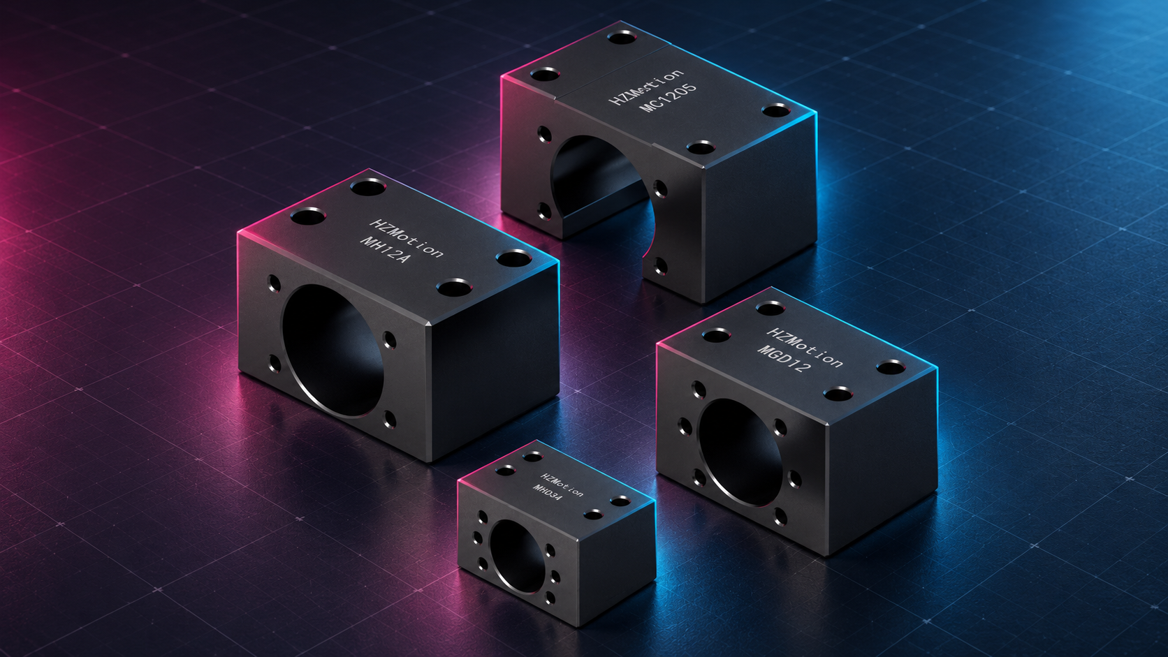
The HZMotion nut bracket manual emphasizes the geometry between the flange mounting face and the table connection face. That geometry helps the nut assemble without imposed misalignment; it does not replace a connection-strength calculation. Check the full MC, MGD, MGS or NH designation, hole layout and orientation. A structural opening is not an adjustment slit for changing nut preload.
This article concerns the joints. Ball screw life, internal nut capacity and complete-axis accuracy require separate checks; satisfactory bolts do not establish those results.
02 / Transfer mechanism
Define contact and location before calculating bolt loads
Preload initially keeps the mating faces compressed. If a joint is designed to transmit transverse force by friction, the force is not necessarily carried entirely as bolt-shank shear before slip. After slip, contact with hole walls, bolts and locating features may change, so the original model may no longer apply. A dowel can carry load only when its fit, material, bearing area and assembly conditions are designed for that function.
V ≤ μ · ΣNc,i
An idealized equilibrium check for one contact plane without slip: V is the in-plane force in N, μ is a confirmed friction coefficient, and N_c,i is the remaining compression in each effective contact region in N. This is not a complete design allowable.This relationship identifies the data needed; it does not justify a capacity claim using an assumed universal friction coefficient. Oil films, finishes, pressure distribution, eccentric loading and preload scatter affect the result. If one edge begins to open, the effective contact region changes. The sum of all initial bolt preloads can no longer simply be inserted into the equation. Use the actual load combinations and safety requirements of the selected design method.
| Mechanism | Required conditions | Assumption to avoid |
|---|---|---|
| Face compression | Effective contact exists in the compressive direction and local material capacity is sufficient. | Reaching tightening torque proves complete seating everywhere. |
| Friction transfer | Residual clamping force, friction conditions and slip requirements are established. | Screw thrust divided by bolt count gives each bolt’s shear load. |
| Dowel, key or stop | The drawing defines load-carrying function, fit and strength. | Every locating feature can carry cyclic shear without further checks. |
| Bolt shear and hole bearing | The model permits the relevant contact and movement, and both fasteners and members are checked. | Bolt strength alone covers edge distance, table material and internal threads. |
Different transfer mechanisms can be valid, but the design must state which one is intended. In a positioning table, slip may already violate the required position stability or reversal repeatability even if the bolts remain well below their strength limit. A strength result and a position-retention result answer different questions.
Follow the load path into the surrounding structure as well. A strong bolt screwed into a thin or weak member does not strengthen that member automatically. Thread stripping, local indentation, hole-edge damage and plate bending deserve their own checks where relevant. Increasing bolt grade without examining these features may leave the controlling limitation unchanged.
03 / Eccentric thrust
Moving a force to the mounting plane also introduces a moment
Define x along the screw and z normal to the table connection plane. A force F along x, applied at a height h from that plane, produces a y-axis moment of magnitude Fh. Mounting the bracket below the table changes the sign of h and can change which edge tends to open. Preserve signs for both directions of screw thrust rather than checking only a positive peak.
My = F · h Q = |My| / b
Use N for F, m for h and b, and N·m for M_y. Q is the magnitude of two opposite resultants separated by b that resist the moment. It is not the tension in each bolt.Independent example: assume a 1,200 N thrust and a 40 mm offset from the joint plane. The moment is 48 N·m. In a simplified equilibrium diagram, opposite tensile and compressive resultants 60 mm apart would each have a magnitude of 800 N. The assumed 60 mm is the distance between those resultant lines; it is not automatically the bolt-row spacing or the outside width of the bracket.
The 48 N·m moment exists together with 1,200 N of in-plane shear. The 800 N value represents only the resisting couple. It does not replace the shear check and cannot be divided between a bolt row without an appropriate model. Actual resultant locations depend on bracket and table bending and the changing contact area. A flexible plate can also introduce prying forces that the simple couple does not capture.
| Assumed offset h | Moment |M_y| | Couple Q with assumed b = 60 mm |
|---|---|---|
| 0 mm | 0 N·m | 0 N; the 1,200 N in-plane shear still exists. |
| 20 mm | 24 N·m | 400 N |
| 40 mm | 48 N·m | 800 N |
| 60 mm | 72 N·m | 1,200 N |
The example shows why layout matters. Bringing the thrust line closer to the joint plane reduces the moment generated by this force. Increasing the effective connection span may also reduce the required couple force. Both changes must be compatible with nut centre height, table stiffness, space and contact conditions; improvised shim stacks are not a substitute for a revised interface design.
For a moving machine, retain the load history as well as the maximum value. Acceleration, braking, process force and gravity may act together or at different times. Document physically credible combinations and reversals. An arbitrary combination of unrelated maxima can conceal the operating case that actually controls slip, opening or fatigue.
04 / Clamp-load changes
Separate increased bolt tension from unloading of the joint
When an external force tends to open a preloaded joint, bolt tension rises while the original compression in the clamped members falls. The two changes need not be equal. A local spring model makes the distinction clear: one bolt and its surrounding clamped material are linear elastic, the axial load is introduced at the outer faces of the members, contact remains closed, and prying, temperature effects and preload loss are omitted.
C = kb / (kb + kc)
Fb = Fv + C·P Nc = Fv − (1 − C)·P
Assume F_v = 8,000 N and C = 0.20. At a local separating load P = 5,000 N, bolt tension is 9,000 N and remaining clamp load is 4,000 N. The bolt gains 1,000 N while the members lose 4,000 N of compression; together these changes balance the 5,000 N external load. P is not the total screw thrust and cannot be obtained merely by dividing that thrust by the bolt count.

The idealized zero-clamp boundary occurs at P = F_v/(1 − C) = 10,000 N. Beyond it, the same straight-line model cannot describe contact. A real bolt group needs the actual load-introduction location, member bending, preload limits and cyclic loading. The lower-preload condition is relevant to separation and slip; the upper-preload condition can govern bolt or contact strength.
Reversing service also requires the bolt load range and fatigue to be checked, not only maximum static tension. Greater preload can help retain contact while also increasing bolt stress or indenting a softer member. The final preload and installation method must come from the controlled joint design. Neither the example preload nor the factor C is a recommended value for a HZMotion bracket.
05 / Assembly and acceptance
Turn model assumptions into inspectable conditions
After analysis, assembly personnel need to know which conditions must be achieved. A bolt size and tightening torque alone do not fully describe preload, friction, contact or position retention. Purchasing, assembly and inspection should refer to the same revisions of the nut, bracket and table drawings, with a traceable tightening method.
- Define load combinationsRecord normal motion, reversal, acceleration and relevant abnormal design cases, including thrust direction, application point and external table loads. Preserve realistic timing rather than assuming every peak occurs together.
- Identify each interface modelState the role of faces, bolts, dowels and stops. Mark possible opening edges, slip directions and locally flexible regions on the drawing.
- Check connection detailsVerify effective thread engagement, blind-hole clearance, counterbores, bearing area, edge distance, bolt grade and table material. Insertion depth is not all effective thread engagement.
- Specify installation conditionsDefine surface and thread condition, lubrication or coating, sequence, tools and records. Thread-locking compound does not compensate for insufficient clamping.
- Verify after final tighteningCheck seating, location and full-stroke motion. Observe joint and motion behaviour at the specified load, speed and temperature; measure relative joint movement when required.
If starting torque or rotational resistance increases after final tightening, use the nut bracket alignment and resistance checks to examine geometric constraint. Reaching the specified installation torque records execution of a procedure; it is not a direct measurement of preload, seating or load capacity.
Retain the load diagram, fastener list, contact conditions, tightening record and verification results. If a joint needs correction, establish the cause of slip, loosening or eccentric loading before restoring it. Repeated retightening is not a complete diagnosis. For initial interface matching, use the MC, MGD, MGS and NH selection guide.
06 / Questions
Nut bracket joint FAQ
Can four bolts each be assigned one quarter of the thrust?
Only when a specific model with suitable symmetry, stiffness and load introduction supports that allocation. The flange and table interfaces differ in orientation and include contact, friction and moments; equal division is not a general rule.
Does adding a dowel remove the need to check bolts?
No. The dowel needs a defined load-carrying role, while bolts still maintain contact and carry the applicable tensile load. Analyse each component according to its fit, stiffness and function.
Does a larger bracket envelope guarantee greater connection capacity?
No. Contact area, section geometry, threads, hole positions, table material and mounting orientation all affect the result. The envelope alone does not establish a rating.
Can the 8 kN preload in the example be used for assembly?
No. It is an assumed input for a local spring model, unrelated to any fastener size, material or product. Determine actual preload and tightening method from the selected joint design.
What information helps HZMotion review a connection?
Provide the nut flange drawing, full bracket designation, table connection drawing, thrust directions and history, application points, orientation, and the fastener, locating-feature and material requirements.