Published:2026-11-10 00:00:00
Updated:
Engineering selection · Technical RFQ
Match neighboring interfaces while the project is still on paper
A ball screw drive may contain only a few component types, yet it passes through design, purchasing, machining and assembly. A correctly selected individual part can still mismatch its neighbor in axis height, hole position, shaft-end length or tool clearance. A useful request for quotation (RFQ) brings those interfaces onto the same drawing and checklist.
01 / Assembly reference
Organize the package around the motion axis and datums
Start with a clear assembly drawing showing the screw axis, fixed and supported ends, nut location, motor, machine datum and motion direction. It need not contain every manufacturing detail at the beginning, but it should explain where each component connects, how loads travel and which relationships require alignment.
| Information layer | What to show | Question it answers |
|---|---|---|
| Operating conditions | Stroke, speed, acceleration, direction, load and center of gravity | What duty must the selection support? |
| Overall datums | Screw axis, guide datum, support positions and nut working region | Which common references define the assembly? |
| Local interfaces | Journals, shoulders, holes, pilots, threads and coupling space | How do neighboring parts connect? |
| Space envelope | Motor outline, cable exit, tools and service paths | Can the installed assembly be adjusted and maintained? |
| Document status | File identifiers, revisions, provisional dimensions and owners | What is fixed, and what remains a quotation assumption? |
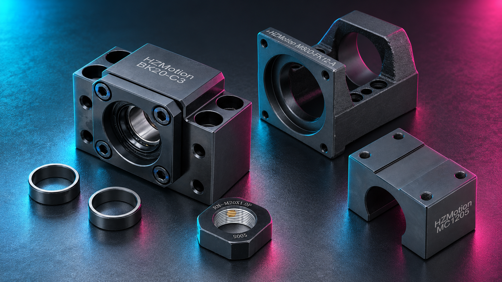
HZMotion support units, A/B/H/L/C/KK motor brackets, MC/MGD/MGS/NH nut brackets and NRA/NR/NF/NK locknuts provide component families for project review. A family name identifies a product range; it does not establish direct compatibility between arbitrary models. Verify dimensions, versions and assembly responsibility individually.
State whether you need individual parts or an assembled unit, then specify the supply scope, assembly and adjustment work, inspection and delivery condition.
02 / Interface dimensions
Provide four information groups together
| Interface group | Information to provide | Matching relationship |
|---|---|---|
| Screw end ↔ support/locking parts | Journal diameter and tolerance, lengths, shoulders, radii/chamfers, threads and end arrangement | Bearing location, axial clamping path, locknut access and axial freedom at the supported end |
| Motor ↔ bracket/coupling | Complete motor model, flange/pilot, hole pattern, shaft diameter/extension and key or other connection | Axis location, both coupling bores, axial gaps, fastening access and cable clearance |
| Screw nut ↔ nut bracket | Nut outline, flange diameter/thickness, hole coordinates, locating features and lubrication port | Bore or opening, flange contact, screw length, axis height and service access |
| All components ↔ machine base | Datums, axis heights, mounting holes/depths, guide relationship and envelope | Closed dimensional stack, contact support, assembly order and maintenance |
“25 mm screw” and “750 W motor” describe only part of the selection. Motors of equal power can have different flanges and shaft extensions; screws of equal nominal diameter can have different end machining, nut forms and support arrangements. Identifying the differences during quotation is more effective than modifying parts during assembly.
Haxis,support = Haxis,nut interface = Haxis,motor interface
Axis heights are directly comparable only when referred to the same machine datum and defined assembly interfaces. Dimensions labeled H on separate drawings may use different origin faces.Consider an independent dimensional example: the support axis is 40 mm above the machine datum, while a nut-bracket axis is 35 mm above its own bottom face. The 5 mm difference does not prove that adding a 5 mm shim is a complete solution. The mounting face, hole pattern, support, stiffness and tolerances still require design. A project may instead use another axis height or a revised interface; the example does not define a supply configuration.
| Frequently omitted detail | Why it matters | Useful presentation |
|---|---|---|
| Shoulder radius and mating chamfer | Matching diameters do not rule out fillet-to-chamfer interference | Shaft-end section and enlarged detail |
| Relative shaft-end positions | Determines coupling grip and axial assembly space | Assembly section with shaft extensions |
| Nut lubrication-port orientation | Tubing or tools may interfere with the bracket or table | Nut view with orientation |
| Locknut diameter and operating space | A part can fit without being accessible for correct tightening | Local view including the tool envelope |
| Hole depth and screw penetration | Controls engagement, bottoming and internal interference | Section, fastener list and dimensional stack |
03 / Supply boundaries
Separate who supplies, who assembles and who verifies
“One ball screw assembly” is not a sufficient scope description. Whether bearings are included, how they are arranged, who provides spacers and locknuts, and whether a coupling is included all affect price and delivery condition. Motor and control equipment should not be assumed. Some HZM worktable catalog entries explicitly identify the motor and CNC system as separately configured; use the confirmed quotation scope for each project.
| Item | Decision to make | Delivery detail to state |
|---|---|---|
| Screw and end machining | Customer supplied, supplier supplied or pending | Drawing revision, completed machining scope and protection |
| Supports and bearings | Housing only, specified bearings included or assembled | Bearing arrangement, assembly responsibility and delivery state |
| Locknuts and spacers | Included, separate line items or customer supplied | Specifications, quantities and mating relationship |
| Motor and nut brackets | Verified standard model or approved drawing | Interfaces, finish and dimensional requirements |
| Coupling, motor and sensors | Select a supply owner for each | Models, connection forms and accessories |
| Assembly and verification | Loose parts, subassembly or agreed complete assembly | Adjustment scope, inspection and reports |
| Documents | Interface/assembly drawings and reports | Revision, language and format |
Expand “accessories included” into a list. If an item is unresolved, mark it pending and name an owner and target date rather than leaving it blank. A proposal with explicit assumptions is usually easier to refine than an apparently complete quotation built on different interpretations.
04 / Revision and acceptance
Make quotation assumptions traceable to inspection
- Build a document packageAssign document IDs and revision numbers to the assembly, shaft-end, motor, nut and mounting drawings and to the RFQ. Distinguish manufacturing drawings from references and provisional dimensions.
- List unresolved interfacesAssign an owner, target date and impact on quotation or lead time. Include necessary assumptions in the quotation attachment.
- Agree supply and acceptanceState whether inspection covers individual dimensions, assembly condition or machine-level positioning. Define methods, conditions and acceptance criteria separately.
- Freeze the order basisList applicable documents at order release. Subsequent changes should identify affected parts, quantities and work already completed, not merely replace one drawing.
- Use the same basis for handoverAssembly, inspection and purchasing need the same revisions. Link delivery records to model, batch or serial identification.
| Acceptance level | Possible requirements | Conditions to agree |
|---|---|---|
| Individual interfaces | Journals, holes, pilots, threads and axis heights | Datums, tolerances and applicable drawings |
| Assembly condition | Assembly scope, axial location, movement, fastening and lubrication | Actual structure, inspection method and responsibility |
| Axis performance | Agreed positioning, repeatability, travel geometry or other metrics | Load, speed, stroke, direction, temperature and measurement method |
| Delivery documents | Reports, assembly drawings and use instructions | Document list, revisions, language and identification |
Conforming component dimensions do not automatically establish machine accuracy. The result also depends on the base, guides, connection stiffness, feedback and control. Any commitment for assembly or performance requires a defined scope under the supplier’s control and mutually agreed verification conditions.
05 / Fillable worksheet
Download the template and mark both known and pending items
Download: Ball Screw Drive Technical RFQ — bilingual CSV
Open the template in a spreadsheet application for engineering and purchasing to complete together. It covers project conditions, the four interface groups, supply scope, acceptance and attachment revisions. Enter the project data, mark unresolved items as pending, and record units, drawing revisions, owners and status.
| Sequence | Recommended action | Useful output for selection |
|---|---|---|
| Enter known duty first | Load, direction, stroke, speed and accuracy objectives | A defined operating case rather than “high precision” |
| Attach four interface groups | Record file names and revisions; mark unknown dimensions pending | Dimensions linked to reference datums |
| Resolve each supply item | Write supplier, customer or pending | Component list and assembly responsibility |
| Review acceptance and revisions | State criteria, conditions, document list and open items | A package ready for technical clarification |
A practical minimum package is an overall assembly drawing, motor drawing, screw-end drawing, nut drawing and completed worksheet. If one is unavailable, identify the gap so the next engineering action is clear.
06 / Frequently asked questions
Six questions from enquiry to order
Can motor power and screw diameter define the complete selection?
No. Shaft-end details, flange, shaft extension, nut outline, machine datums, operating conditions and space are also needed. Power and nominal diameter are only part of the input.
Does a model list prove the components can be assembled?
No. Check current drawings for neighboring interfaces, axes and heights, fastening and tool space, and the actual delivery condition.
Does a support-unit quotation automatically include bearings and locknuts?
Do not assume it. Bearing inclusion and arrangement, locking parts and spacers should be explicit quotation and purchase items.
Can an axis-height difference be solved with a shim?
Only through a confirmed design. Location, holes, support, stiffness and tolerances matter as well as height. A correct arithmetic difference does not validate the connection.
Can an RFQ begin before drawings are released?
Yes, with explicit assumptions. Mark provisional dimensions, pending items, owners and revisions; freeze the applicable documents and supply scope before order release.
Does the RFQ worksheet replace manufacturing drawings?
No. It organizes conditions, revisions and responsibility. Approved drawings and technical requirements still define manufacturing details.