Published:2026-08-16 09:30:00
Vertical ball-screw actuators
The motor carries the load in motion, the brake holds after stopping, and mechanical restraint protects service work
Think of a vertical actuator as a small lift. Gravity always pulls the carriage and payload downward. Servo torque supports the load while available; if torque disappears before the brake has established holding, the payload can back-drive the screw and move down.
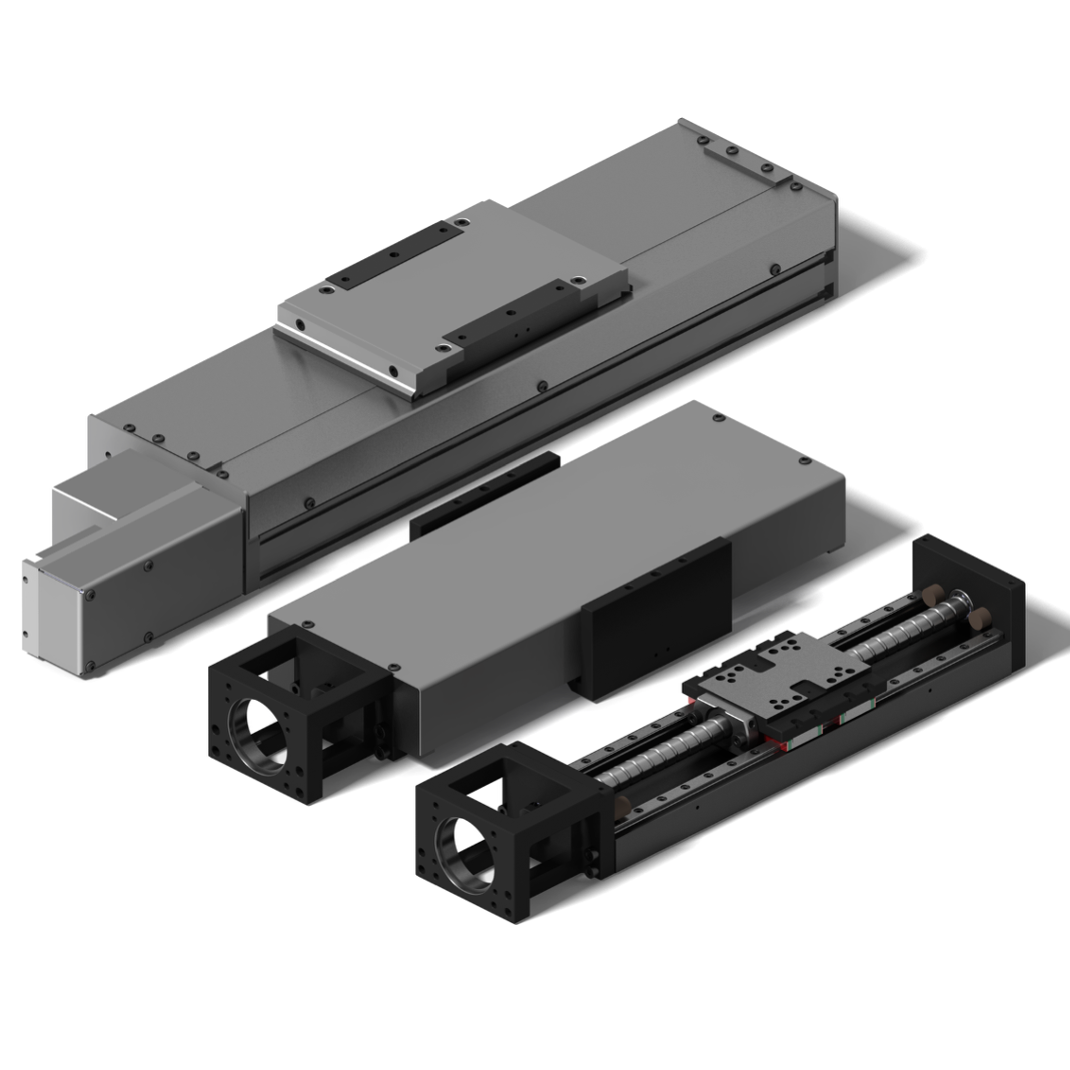
01 / Follow the mechanical path
Without motor torque, the load can turn the screw backward
Ball screws transmit force through rolling balls. Low friction gives high efficiency but also allows back-driving. Whether the axis moves immediately, and how fast, depends on friction, balancing, the brake and mechanical condition; however, the design must not assume self-locking.
The carriage, tooling and workpiece create a continuous downward force.
The payload pulls the carriage and screw nut downward.
Linear nut motion drives screw rotation through the rolling elements.
If neither motor torque nor established brake holding is available, the axis can descend.
Practical conclusion: a small lead may reduce back-driving tendency, but it is not a safety-rated self-locking assumption. THK also calls for fall-prevention measures in inclined or vertical use.
02 / Three layers
Separate motion, stopped holding and maintenance safety
Motion, positioning, gravity compensation and controlled deceleration. Motor torque carries the vertical load while enabled.
Normally clamps the motor shaft after the axis has stopped. It is generally not the service brake for every deceleration.
Validated clamping, drop prevention or support where people may enter a hazard zone or brake/transmission failure must be covered.
A regeneration resistor does not hold position: descent and deceleration return potential and kinetic energy to the drive. The DC bus or resistor manages energy; it does not replace a holding brake or mechanical restraint.
03 / Normal start and stop
Build supporting torque before release; stop before engagement
Normal start
- Enable the servoEstablish position control and the torque needed to support gravity.
- Confirm drive readyVerify feedback, torque availability and absence of faults.
- Release the brakeUse the drive's specified brake interlock and wait for release.
- Command motionIssue position or speed commands only after release is complete.
Normal stop
- Controlled decelerationThe servo first slows the axis to near zero.
- Command brake engagementLet the holding brake begin to close after the axis has stopped.
- Keep motor torqueThe motor continues carrying the load during mechanical engagement.
- Remove torque lastServo off or enter the relevant safe state only after holding is established.
Do not copy one fixed delay: release and engagement times depend on the motor, brake, voltage, temperature and wear. Follow the selected servo manual and validate on the machine. Prefer the drive's brake interlock instead of improvising the sequence with a general PLC output.
04 / Power loss and emergency stopping
Normal stopping, controlled emergency stopping and sudden power loss are different cases
| Case | What happens on the axis | What to verify |
|---|---|---|
| Normal stop | The drive remains in control and can decelerate before brake engagement. | Zero-speed decision, brake action time and torque overlap. |
| Controlled emergency stop | If control remains available, the axis can decelerate before brake engagement and torque removal. | Actual stopping time, brake sequence and the machine safety architecture. |
| Sudden power loss or severe fault | The drive may not decelerate; the spring-applied brake may close while the axis still moves. | Permitted emergency stops, dynamic energy, wear and allowed drop distance. |
| Personnel access or maintenance | Motor, brake, coupling and screw cannot be assumed never to fail. | Lower the load or use validated mechanical support, clamping or drop prevention. |
STO does one thing: it prevents the motor from producing torque. It does not stop the axis or support a vertical load. Where applicable, SS1 performs controlled deceleration before STO; SBC/SBT brake control and testing depend on the machine risk assessment and selected safety system.
05 / A simple example
A 50 kg load with 10 mm lead already creates meaningful screw torque
Assume 50 kg total vertical moving mass, a 10 mm screw lead and direct motor coupling. First consider ideal gravity only:
0.78 N·m is not the brake selection: actual sizing includes acceleration, process force, balancing, transmission efficiency, worst voltage and temperature, wear, brake action time and vendor-required margins. The example simply shows how an ordinary vertical load continually pushes the screw and motor shaft backward.
Provide at least these five data groups for actuator, motor and safety selection
- Total moving massCarriage, tooling, workpiece, cable and maximum/minimum payload.
- Motion profileStroke, speed, acceleration, cycle, dwell and orientation.
- Brake conditionsHolding torque, engagement/release time, worst voltage and temperature, and permitted duty.
- Fault boundaryAllowed drop distance, emergency dynamic engagement and wear monitoring.
- Personnel riskPossible access below the load and independent maintenance support or drop prevention.
Capacity, timing and wear still matter, and a motor-shaft brake cannot cover every transmission break.
STO removes motor torque and can remove the force supporting a vertical load.
Do not credit friction as a safety function; design for possible back-driving.
It reduces imbalance but adds inertia and has its own failure modes.
06 / Quick answers
Vertical ball-screw actuator questions
Can the motor brake stop every cycle?
Generally it should not. Most servo brakes are holding brakes and normal deceleration belongs to the motor. Any permitted occasional emergency engagement must follow the motor's energy and cycle limits.
Will the brake catch instantly after power loss?
A brake has a mechanical engagement time, so some movement may occur. Validate allowed drop distance against load, speed, brake capability and machine-level measures.
Can maintenance rely only on STO and the motor brake?
They are not automatically maintenance supports. Lower the suspended load or use validated mechanical support and follow the machine's isolation and lockout procedure.